
"Cleaning Article, Method of Fluffing Cleaning Article, and Method of Producing Cleaning Article"

a cleaning article and fluffing technology, applied in the field of cleaning articles, can solve the problems of poor cleaning performance, poor conformability of articles to an uneven surface of an object to be cleaned, and inferior fluffing capabilities and recovery from compression in a cleaning operation, and achieve superior cleaning performance, high fluffing capabilities, and high conformability

Active Publication Date: 2010-06-24
KAO CORP
View PDF47 Cites 32 Cited by
  • Summary
  • Abstract
  • Description
  • Claims
  • Application Information

AI Technical Summary

Benefits of technology

[0008]The present invention provides a cleaning article the fiber layers of which exhibit high fluffing capabilities and recovery from compression, which is highly conformable to an uneven surface of an object being cleaned, is given due consideration for user's convenience, and is superior in cleaning performance. The present invention also provides a method of fluffing the cleaning article and a method of producing the cleaning article.

Problems solved by technology

Since the cleaning article of Patent Document 2 has the fiber layer bonded to the substrate sheet by a plurality of continuous linear seals, the fiber layer is inferior in rising or fluffing capabilities and recovery from compression in a cleaning operation.
Therefore, the article has poor conformability to an uneven surface of an object to be cleaned, namely poor cleaning performance.
The cleaning article of Patent Document 3 includes strips in addition to the fiber layer and the substrate sheet so that the fiber bundle fails to make effective contribution to cleaning.
The cleaning article of Patent Document 4, having a fiber layer on only one side, is useful for cleaning purposes on only one side thereof, which makes a cleaning operation cumbersome.

Method used


Image

  • "Cleaning Article, Method of Fluffing Cleaning Article, and Method of Producing Cleaning Article"
  • "Cleaning Article, Method of Fluffing Cleaning Article, and Method of Producing Cleaning Article"
  • "Cleaning Article, Method of Fluffing Cleaning Article, and Method of Producing Cleaning Article"

Examples


first embodiment

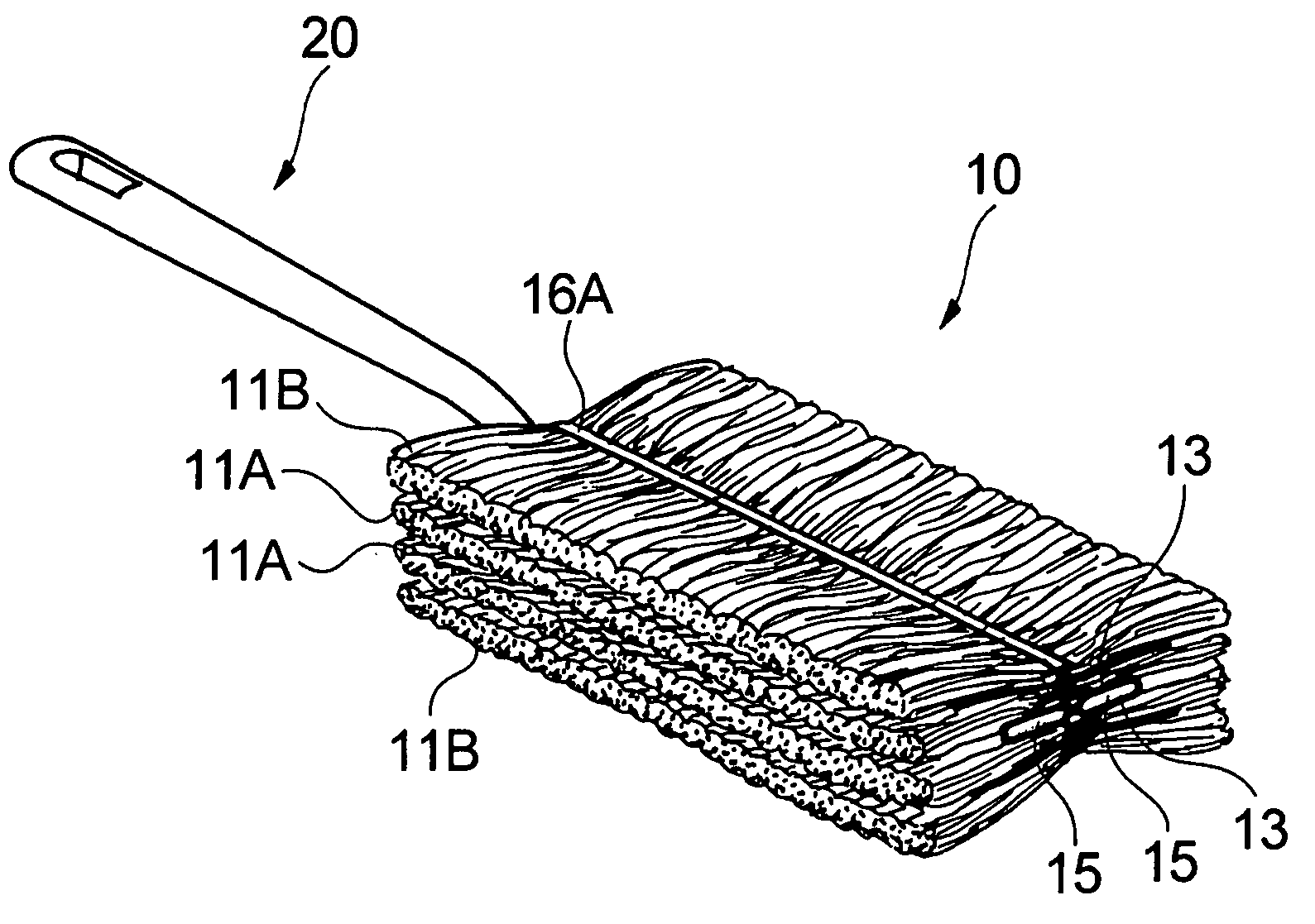
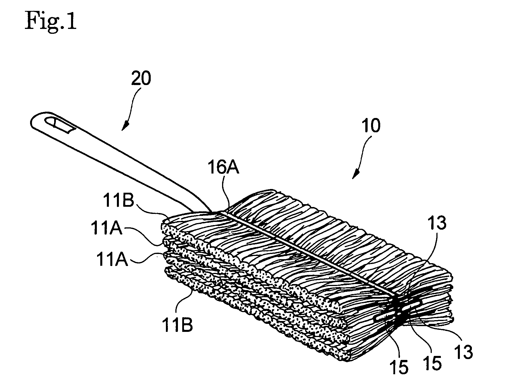
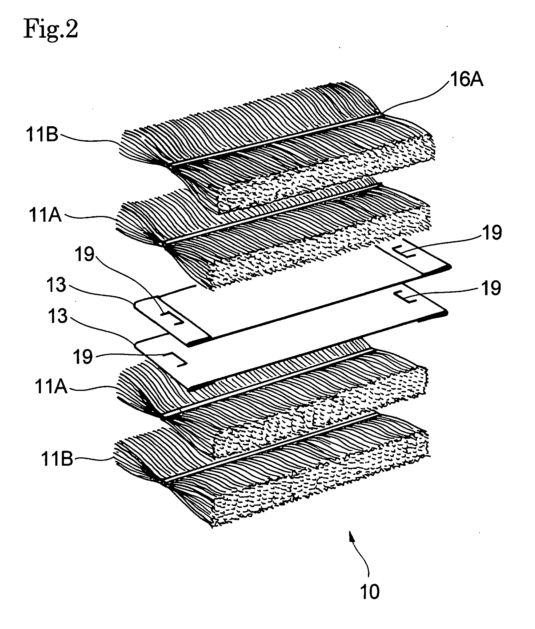
[0049]The first fiber layers 11A are closer to the pocket-forming sheets 13 than any other fiber layers 11. The second fiber layers 11B are each a fiber layer present on the outer side of the first fiber layer 11A. Accordingly, the mop 10 of the first embodiment has a stack of four fiber layers, i.e., the second fiber layer 11B and the first fiber layer 11A on the upper side of the pockets and the first fiber layer 11A and the second fiber layer 11B on the lower side of the pockets 14 in the order from the upper to lower sides.

[0050]The fiber layers 11 are each formed of an oriented fiber bundle with a prescribed thickness. The fiber bundle is substantially oriented in the lateral direction of the pockets 15. Accordingly, the first fiber layers 11A and the second fiber layers 11B are stacked with the fiber orientation direction substantially perpendicular to the longitudinal direction of the pocket-forming sheets 13. The fiber layers 11 are each a nearly rectangular in a plan view a...

third embodiment

[0106]At least one fiber layer 11 formed of a fiber bundle is disposed on each of the upper and lower sides of the pockets 15, i.e., the facing pocket-forming sheets 13. In the third embodiment, two fiber layers 11, i.e., a first fiber layer 11A and a second fiber layer 11B are disposed on the upper side of the pockets 15 and two other fiber layers 11, i.e., a third fiber layer 11C and a fourth fiber layer 11D are disposed on the lower side of the pockets 15.

[0107]Numerical reference 13 will be used in describing particulars common to the first pocket-forming sheet 13A and second pocket-forming sheet 13B. Numerical reference 11 will be used in describing the first fiber layer 11A, second fiber layer 11B, third fiber layer 11C, and fourth fiber layer 11D in common. In describing the first fiber layer 11A and third fiber layer 11C in common, these layers will be identified with term “inner fiber layers 11P”. In describing the second fiber layer 11B and fourth fiber layer 11D in common...

fourth embodiment

[0157]The holder 20 to which the mop of the fourth embodiment is to be attached may be either two-forked as illustrated in FIG. 5 or nonforked as in FIG. 9 as long as its width is practically the same as that of the pocket 15.

[0158]The fourth embodiment achieves the same effects as in the third embodiment. Additionally, when the insertion portion of the holder 20 is unforked as illustrated in FIG. 9, the pocket has its rigidity increased by the holder 20 to exhibit improved maneuverability in cleaning hard-to-reach spaces such as corners of rooms and gaps between walls and furniture or scraping tough dirt off a surface of an object being cleaned.

[0159]The method of making a cleaning article according to the present invention will now be described taking, for instance, the production of the mop 10 of the fourth embodiment shown in FIG. 14. FIGS. 15(a) through 20(b) will be referred to. In FIG. 19, the step for making a second continuous form subassembly 32B is substantially identical...


PUM

PropertyMeasurementUnit
Lengthaaaaaaaaaa
Widthaaaaaaaaaa

Abstract

A cleaning article 10 having a flat tubular pocket 15 and attachable to a holder by inserting the holder into the pocket 15. The pocket 15 is formed by joining pocket-forming sheets 13 facing each other. At least one fiber layer formed of a fiber bundle, accordingly two fiber layers 11A and 11B are provided on each of the upper and lower sides of the pocket 15 of the pocket-forming sheets 13. Each of the first fiber layers 11A closest to the pocket-forming sheets 13 is joined to the respective pocket-forming sheet 13 by a continuous central linear seal 16A continuously extending in the longitudinal direction in a laterally middle portion and a discontinuous side seal 16B discontinuously extending in the longitudinal direction at a position laterally spaced away in at least one of the lateral directions from the central continuous linear seal 16A.

Description

TECHNICAL FIELD[0001]The present invention relates to a cleaning article having a holder-receiving pocket and attachable to a holder by inserting the holder into the pocket, a method of fluffing the cleaning article, and a method of producing the cleaning article.BACKGROUND ART[0002]Cleaning articles having a holder-receiving pocket (hereinafter simply referred to as a pocket) and attachable to a holder by inserting the holder into the pocket are known, e.g., from Patent Document mentioned below[0003]Cleaning articles having a fiber layer formed of a fiber bundle on both the upper and lower sides of a substrate sheet are also known. The fiber layer is generally bonded to the substrate sheet by a plurality of continuous linear seals as disclosed, e.g., in Patent Documents 2 and 3.[0004]Cleaning articles having a fiber layer formed of a fiber bundle on one side of a substrate sheet are also known, in which the fiber layer and the substrate sheet are bonded by linear bonding and discon...

Claims


Application Information

Patent Timeline
IPC IPC(8): A47L25/00B23P17/04
CPCA47L13/20Y10T29/49826D21H27/30A47L13/38A47L13/16A47L13/24
Inventor TAKABAYASHI, KEIMAWADA, MINORUOMORI, CHIHARUSHIZUNO, AKIHITO
Owner KAO CORP
Learn More