Capacitance diaphragm gauge and vaccum apparatus

a technology of capacitance diaphragm and gauge, which is applied in the direction of measuring devices, instruments, and fluid pressure measurement using capacitance variation, etc., can solve the problems of error and increase the cost of the gauge itsel

Inactive Publication Date: 2010-06-24
CANON ANELVA CORP
View PDF11 Cites 17 Cited by
  • Summary
  • Abstract
  • Description
  • Claims
  • Application Information

AI Technical Summary

Benefits of technology

[0025]It is an object of the present invention to provide a capacitance diaphragm gauge which can perform accurate pressure measurement regardless of mount conditions for the gauge.

Problems solved by technology

As described above, since a capacitance diaphragm gauge is generally assembled and adjusted while the connection fitting for a vacuum apparatus faces downward, errors occur when the gauge is used at other inclination angles.
This inevitably leads to an increase in the cost of the gauge itself.

Method used


Image

  • Capacitance diaphragm gauge and vaccum apparatus
  • Capacitance diaphragm gauge and vaccum apparatus
  • Capacitance diaphragm gauge and vaccum apparatus

Examples


Embodiment Construction

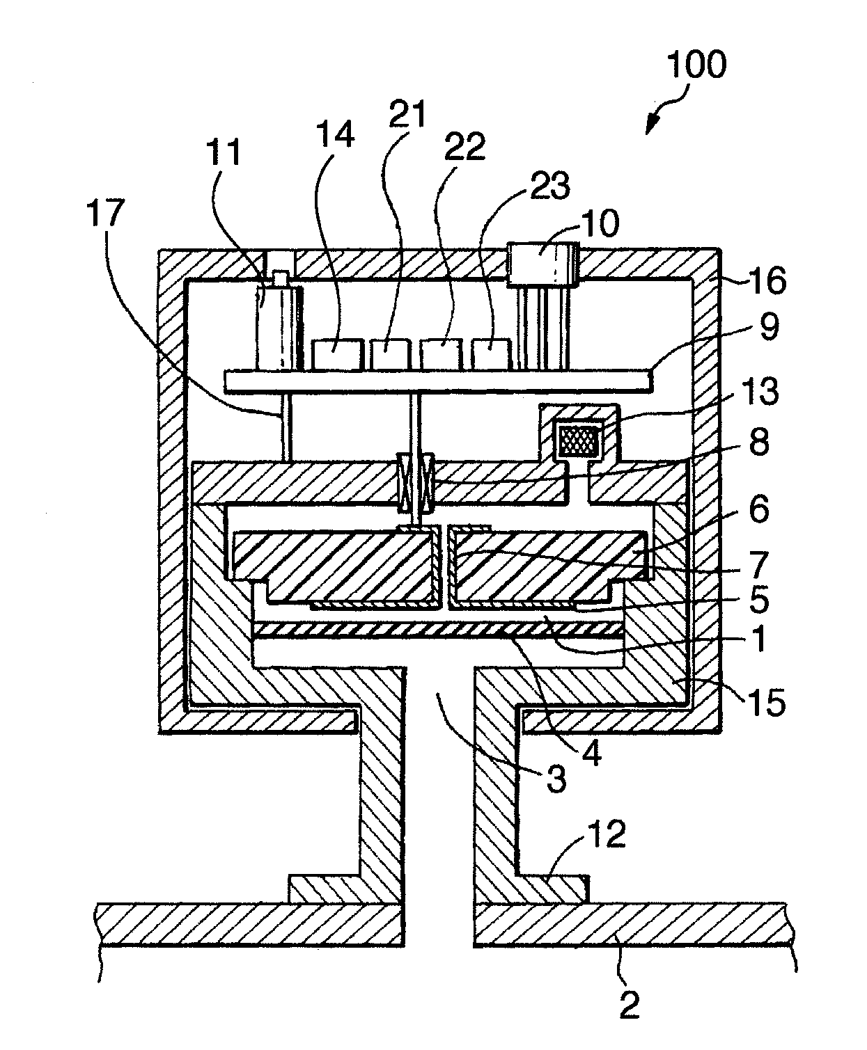
[0039]The best mode for carrying out the present invention will be described in detail below with reference to the accompanying drawings. FIG. 1 is a schematic sectional view showing an embodiment of a capacitance diaphragm gauge according to the present invention. The same reference numerals as in FIG. 1 denote the same parts in FIG. 5.

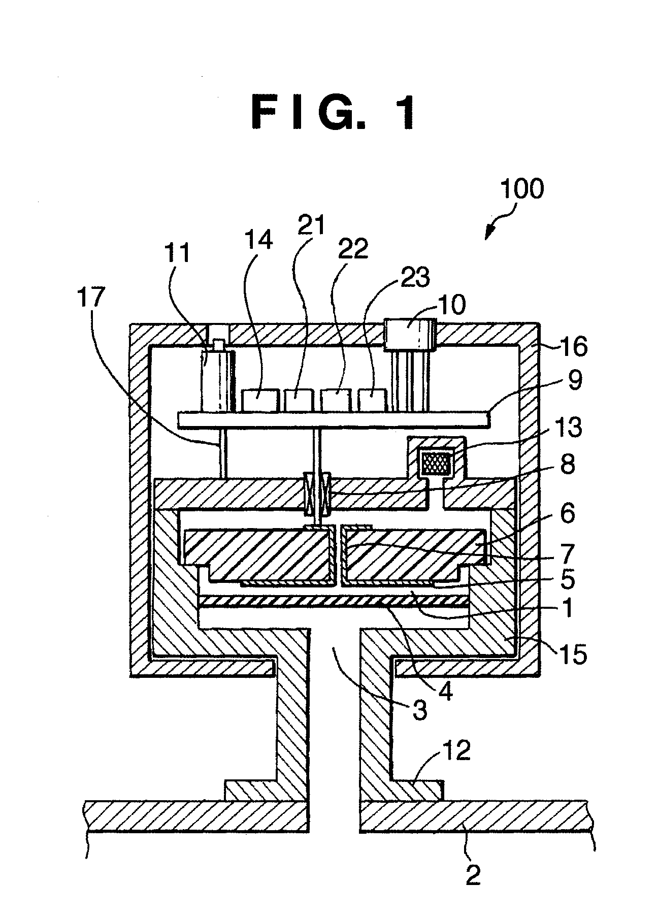
[0040]On the circuit board 9 shown in FIG. 1, the zero point adjustment potentiometer 11, an inclination angle sensor 14, the capacitance detection unit 21, a pressure correction unit 22, and a storage unit 23 are fixed. FIG. 1 differs from FIG. 5 in that the capacitance diaphragm gauge includes the inclination angle sensor 14, and the storage unit 23. The pressure correction unit 22 and the storage unit 23 correct a pressure measurement value based on the inclination angle of a capacitance diaphragm gauge 100 which is detected by the inclination angle sensor 14, as will be described later. A method of correcting a pressure measurement value by using...


PUM

PropertyMeasurementUnit
inclination angleaaaaaaaaaa
pressuresaaaaaaaaaa
diameteraaaaaaaaaa

Abstract

A capacitance diaphragm gauge includes an inclination angle sensor which detects the inclination angle of the gauge. The pressure dependences of capacitance obtained when the capacitance diaphragm gauge is mounted on a vacuum apparatus at the first inclination angle (+90°), the second inclination angle (0°), and the third inclination angle (−90°) are stored in a storage unit in advance. A pressure measurement value is then corrected based on the inclination angle information detected by the inclination angle sensor and the capacitance-pressure characteristic data is actually measured at the first, second and third inclination angles, and stored in the gauge.

Description

BACKGROUND OF THE INVENTION[0001]1. Field of the Invention[0002]The present invention relates to a capacitance diaphragm gauge used for pressure measurement and a vacuum apparatus, more particularly, to a capacitance diaphragm gauge suitable for pressure measurement in a vacuum apparatus such as a sputtering apparatus or an etching apparatus.[0003]2. Description of the Related Art[0004]FIG. 5 is a view schematically showing the capacitance diaphragm gauge disclosed in the specification of U.S. Pat. No. 4,785,669. Referring to FIG. 5, reference numeral 100 denotes a capacitance diaphragm gauge to measure a pressure inside a vacuum apparatus 2; and 16, a case covering the capacitance diaphragm gauge 100. The case 16 incorporates a getter 13, an insulting member 6, a fixed electrode 5, a circuit board 9, and the like.[0005]A conductive housing 15 incorporates a reference pressure chamber (vacuum sealed chamber) 1 which is sealed while its interior is kept at a high vacuum by the getter...

Claims


Application Information

Patent Timeline
Patent Type & Authority Applications(United States)
IPC IPC(8): G01L9/12
CPCG01L19/0092G01L9/0072G01L19/02
Inventor MIYASHITA, HARUZO
Owner CANON ANELVA CORP
Why Eureka
Try Eureka