Fuel-injection device

a fuel injection and injection tube technology, applied in the direction of liquid fuel feeders, machines/engines, mechanical equipment, etc., can solve the problems of increased radial expansion of the fuel injector, increased installation space requirements, and lift changes of the valve needle, so as to achieve secure and effective fixing, simple and cost-effective production, and simple design

Active Publication Date: 2010-06-24
ROBERT BOSCH GMBH
View PDF18 Cites 24 Cited by
  • Summary
  • Abstract
  • Description
  • Claims
  • Application Information

AI Technical Summary

Benefits of technology

[0012]The fuel-injection device according to the present invention has the advantages of a simple design, simple and cost-effective production, and facilitates a very secure and effective fixing of the fuel injector in a receiving borehole of a cylinder head. The mounting of the fuel injector on the fuel rail, according to the present invention, has, above all, the advantage that hydraulic forces are transferred directly to the fuel rail. The installation of the fuel rail-fuel injector composite may advantageously take place in that the fuel injector does not axially touch the cylinder head at any place, so that structure-borne noise bridges are avoided that cause or reinforce noises.

Problems solved by technology

Particularly disadvantageous in the mounting device known from German patent document DE 29 26 490 A1 is the warping effect of the various mounting elements on the fuel injector.
The flux of force generated in the fuel injector results in deformations and thus in lift changes of the valve needle and even in jamming, as well as in a compressive or bending load on the housing components, which usually have thin walls and are welded to one another at several points.
Furthermore, any mounting measure, for example by a contact flange, leads to an increase in the radial expansion of the fuel injector and thus to higher space requirements in the installation.
These construction types are suitable exclusively for intake manifold injection, but not for direct injection in which the fuel injectors are inserted directly into the receiving boreholes of the cylinder head.

Method used


Image

  • Fuel-injection device
  • Fuel-injection device
  • Fuel-injection device

Examples


Embodiment Construction

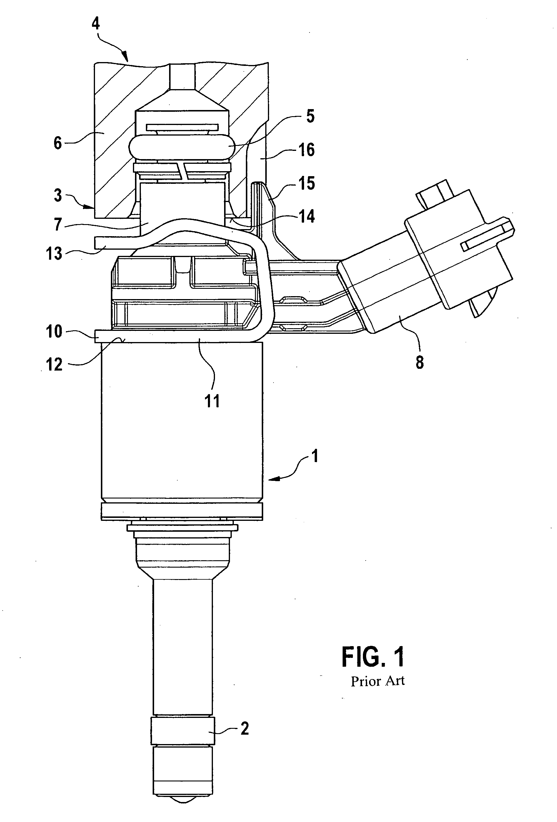
[0023]FIG. 1 shows a conventional example of a fuel injector, in which a valve is shown in a side view in the form of a fuel injector 1 for fuel-injection systems of mixture-compressing internal combustion engines having externally supplied ignition. Fuel injector 1 is executed as a so-called top feed injection valve, and is thereby a part of a fuel-injection device. At its downstream end, fuel injector 1, which is embodied as a directly injecting fuel injector for the direct injection of fuel into a combustion chamber of the internal combustion engine, is installed in a receiving bore of a non-depicted cylinder head. A sealing ring 2, in particular made of Teflon®, provides optimal sealing between fuel injector 1 from the wall of the cylinder head.

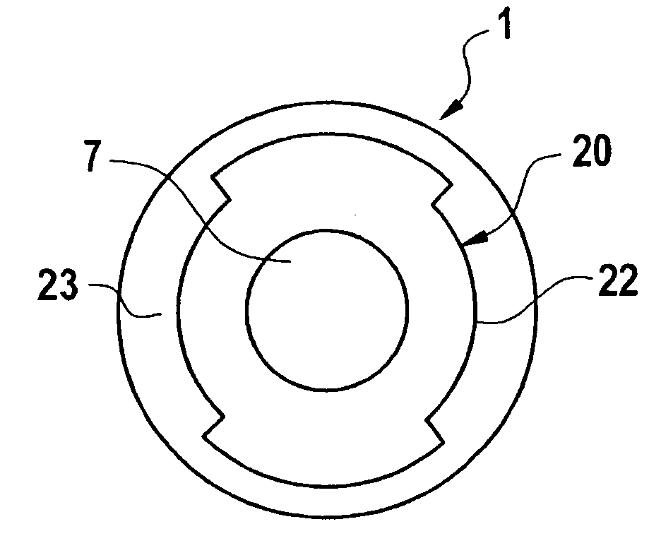
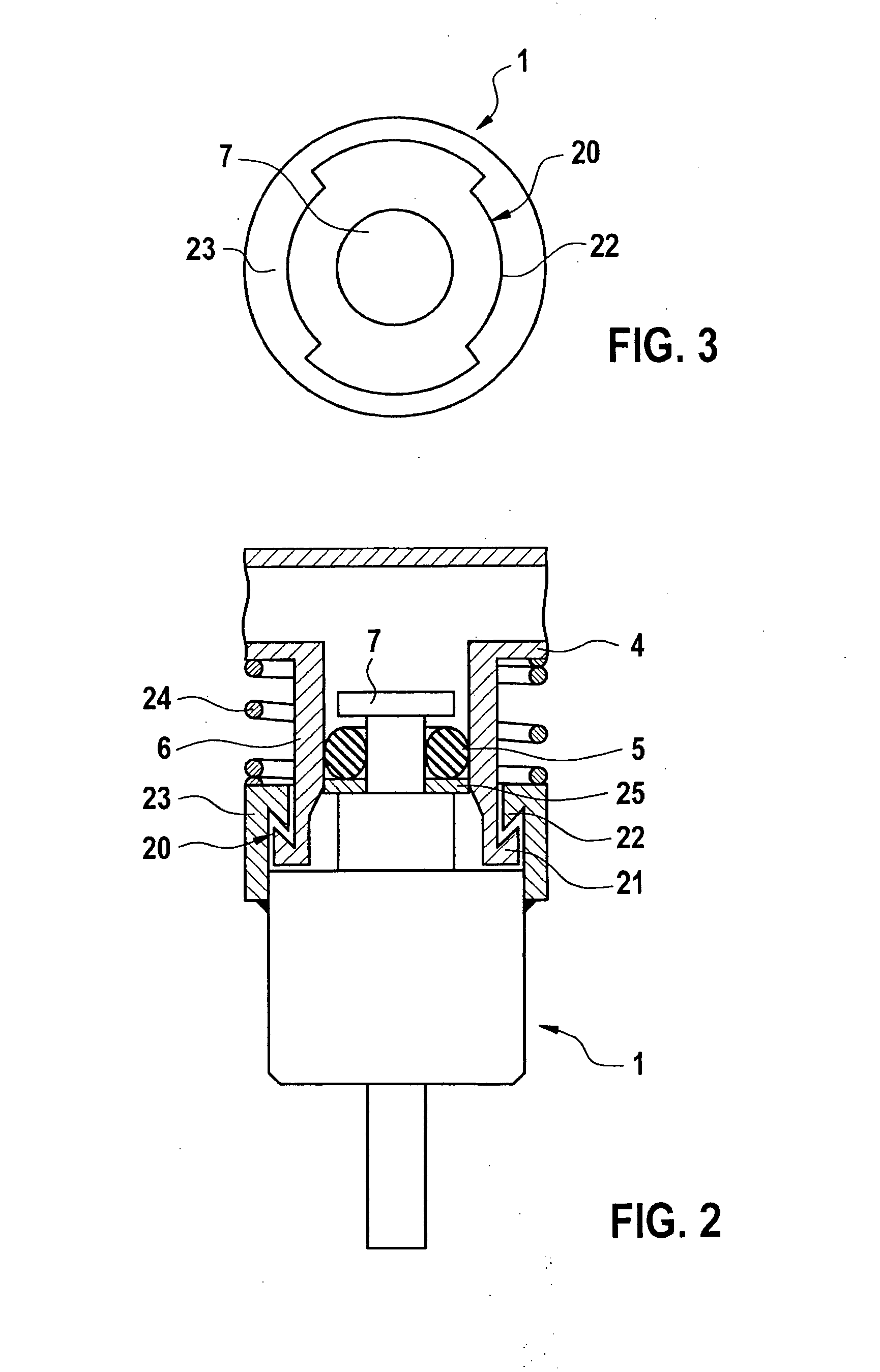
[0024]At its intake end 3, fuel injector 1 has a plug connection to a fuel rail 4, which is sealed by a sealing ring 5 between a pipe connection 6 of fuel rail 4, shown in cross section, and an inlet connection 7 of fuel injector 1. Fuel ...


PUM


Abstract

A fuel-injection device includes at least one fuel injector, one receiving bore-hole for the fuel injector, and one pipe-shaped pipe connection of a fuel rail. The fuel injector is pushed into the interior of the pipe connection by an upstream inlet connection. A bayonet closure ensures that the fuel injector is fastened in the pipe connection of the fuel rail in a secure and detachable manner.

Description

BACKGROUND OF THE INVENTION[0001]1. Field of the Invention[0002]The present invention relates to a fuel-injection device, and relates more particularly to mounting of the fuel-injection device.[0003]2. Description of Related Art[0004]A mounting device for mounting a fuel injector on an intake manifold is already known from German patent document DE 29 26 490 A1, according to which a mounting element axially fixes the fuel injector to the fuel rail or to a plug nipple, the mounting element being designed as a U-shaped securing clasp having two legs which are elastic in the radial direction. In the assembled state, the securing clasp engages in matching recesses of the plug nipple and is snapped into place in a recess in a connection piece of the fuel injector, the recess being designed as an annular groove. The axial clearance between the recesses and the securing clasp as well as between the annular groove and the securing clasp should be kept small, in order to achieve accurate fix...

Claims


Application Information

Patent Timeline
Patent Type & Authority Applications(United States)
IPC IPC(8): F02M69/46F02M61/14
CPCF02M61/14F02M69/465F02M2200/8023F02M2200/858
Inventor FISCHER, MICHAELLANG, PETERROESCH, HAUKE
Owner ROBERT BOSCH GMBH
Why Eureka
Try Eureka