Lighting system for cooking appliance

Active Publication Date: 2010-06-24
WHIRLPOOL CORP
View PDF10 Cites 4 Cited by
  • Summary
  • Abstract
  • Description
  • Claims
  • Application Information

AI Technical Summary

Benefits of technology

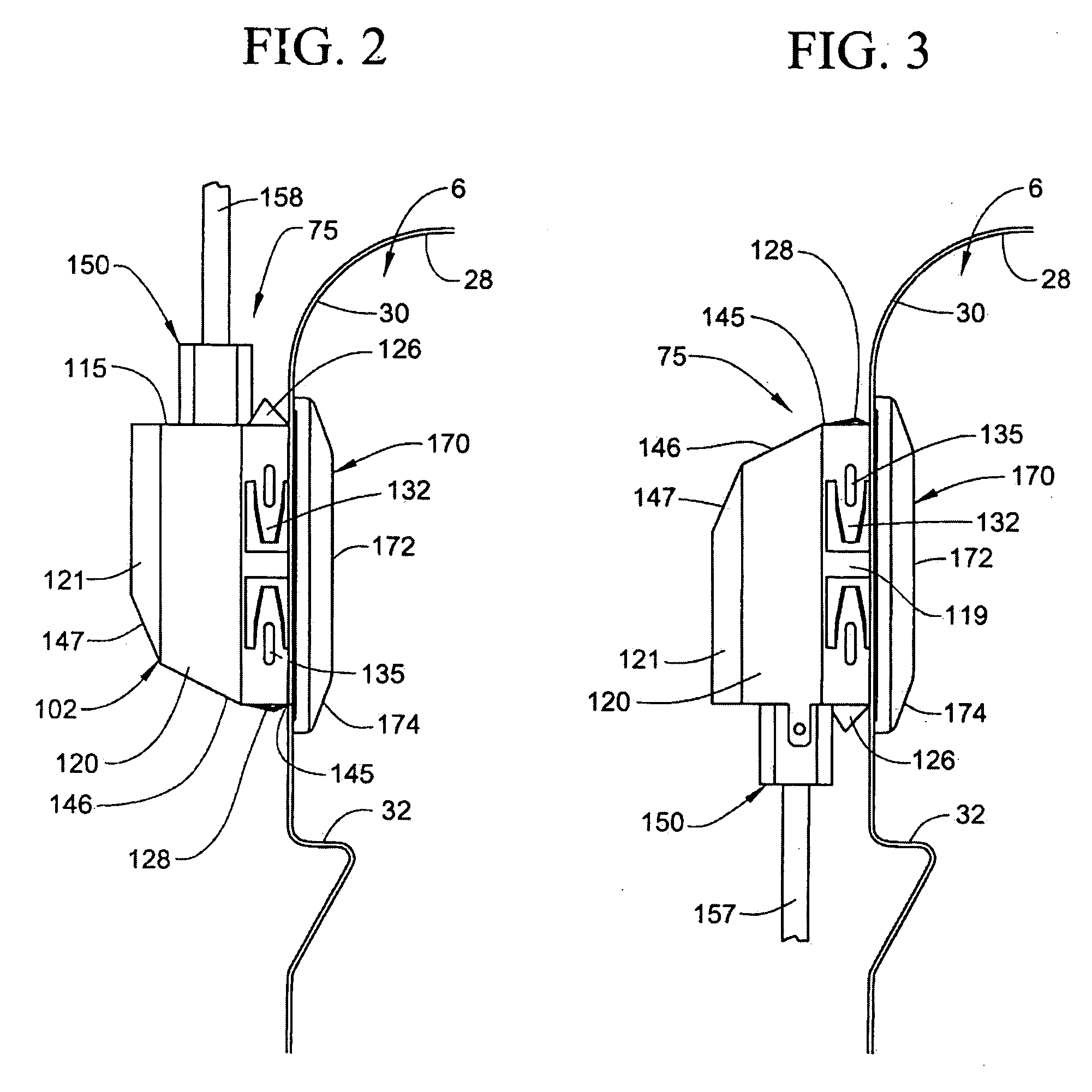
[0006]The present invention is directed to providing a lighting unit or fixture for use in illuminating an oven cavity wherein the lighting unit is internally, asymmetrically constructed, yet externally, substantially symmetrically constructed. Due to the symmetrical external construction, the lighting unit can be readily mounted in an oven cavity in multiple co

Problems solved by technology

Therefore, consumers are not able to alter the available light intensity, at least unless the appliance includes electrical circuitry enabling the lighting unit to receive adjustable current levels.
Instead, essentially universally, a consumer will make a purchase based on other characteristics of the appliance and the available lighting intensity is not a variable option.
As the need to have different lighting

Method used


Image

  • Lighting system for cooking appliance
  • Lighting system for cooking appliance
  • Lighting system for cooking appliance

Examples


Embodiment Construction

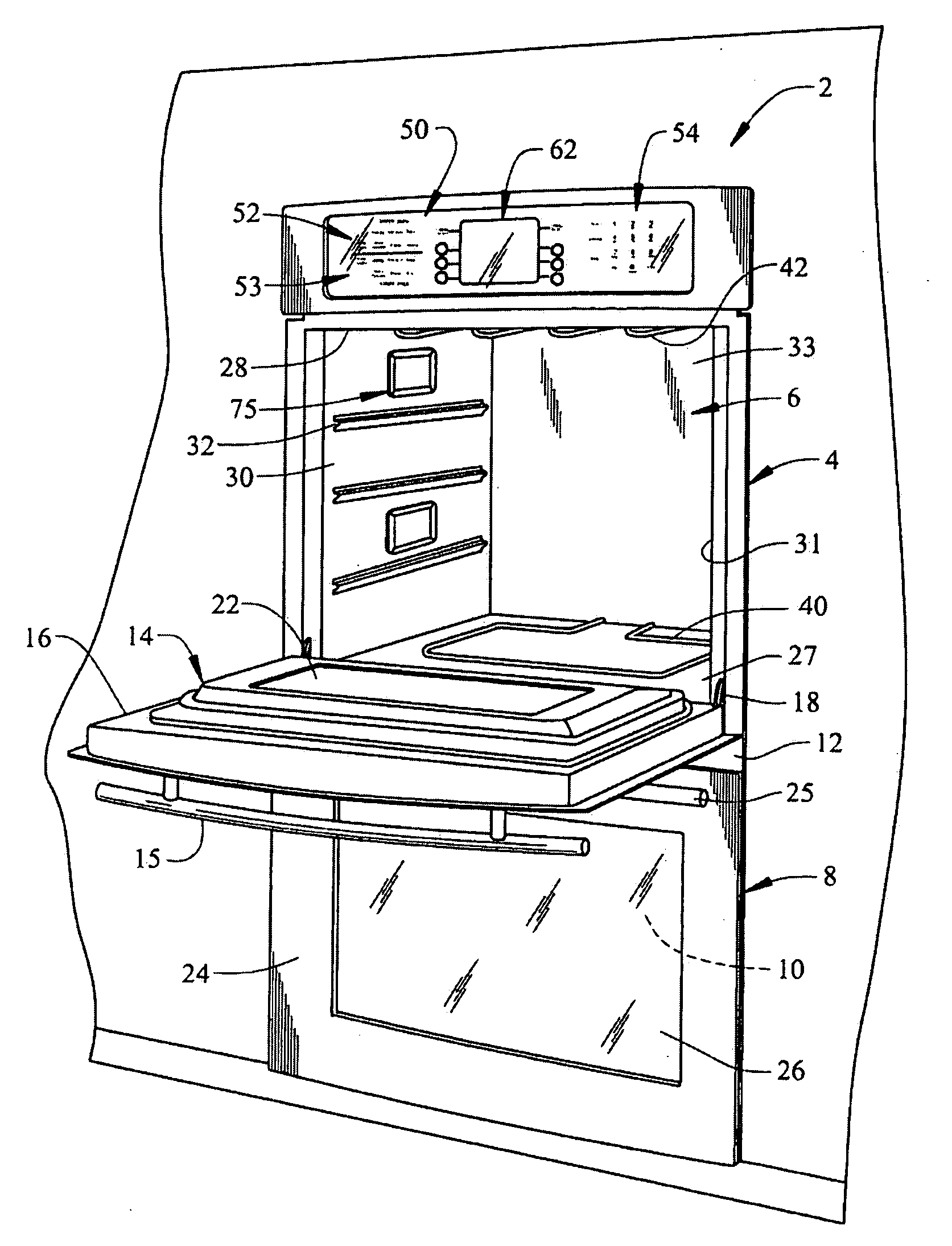
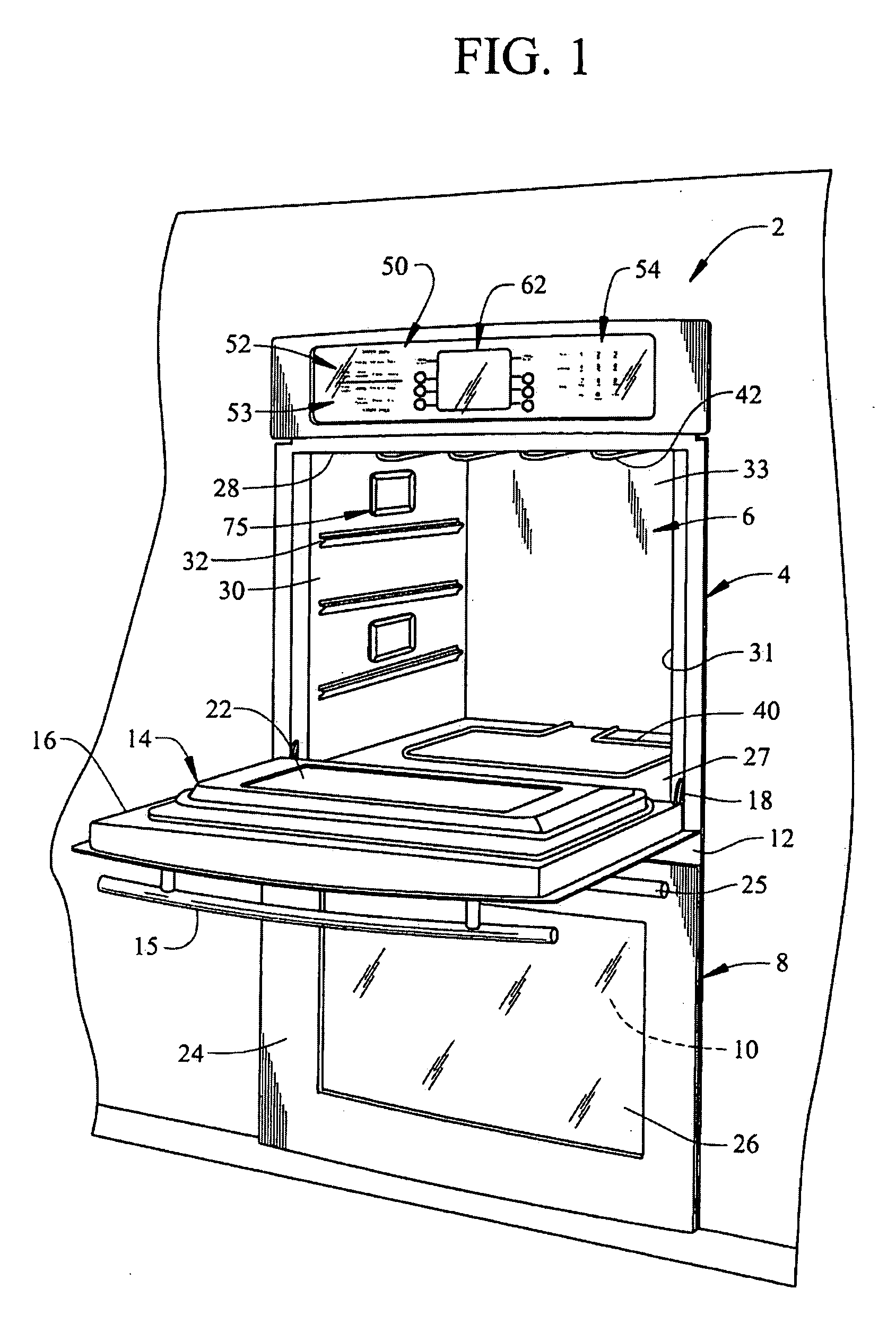
[0013]With initial reference to FIG. 1, a cooking appliance constructed in accordance with the present invention is generally indicated at 2. Cooking appliance 2, as depicted, constitutes a double wall oven. However, it should be understood that the present invention not limited to this model type and can be incorporated into various types of oven configurations, e.g., cabinet mounted ovens, as well as both slide-in and free standing ranges. In any event, in the embodiment shown, cooking appliance 2 constitutes a dual oven wall unit including an upper oven 4 having upper oven cavity 6 and a lower oven 8 having a lower oven cavity 10. Cooking appliance 2 includes an outer frame 12 for supporting both upper and lower oven cavities 6 and 10.

[0014]In a manner known in the art, a door assembly 14 is provided to selectively provide access to upper oven cavity 6. As shown, door assembly 14 includes a handle 15 at an upper portion 16 thereof. Door assembly 14 is adapted to pivot at a lower ...


PUM

PropertyMeasurementUnit
Fractionaaaaaaaaaa
Angleaaaaaaaaaa
Shapeaaaaaaaaaa

Abstract

A lighting unit for use in illuminating an oven cavity is internally, asymmetrically constructed and externally, substantially symmetrically constructed. Due to the symmetrical external construction, the lighting unit can be readily mounted in an oven cavity in multiple configurations to establish varying levels of illumination depending on the selected mounting arrangement. In particular, the lighting unit can be rotated prior to insertion in a side wall opening of the oven cavity, with the illumination intensity varying depending on the selected mounting position. In one preferred embodiment of the invention, the outer shell is rectangular in shape to establish two distinct, potential mounting positions upon rotation of the lighting unit 180°, with the level of illumination varying in the order of at least 45% between the two mounting positions.

Description

BACKGROUND OF THE INVENTION[0001]1. Field of the Invention[0002]The present invention pertains to the art of cooking and, more particularly, to a lighting system employed in a cooking appliance.[0003]2. Description of the Related Art[0004]Many cooking appliances incorporating oven cavities are provided with doors including transparent portions which enable a user to view the progress of a cooking operation without requiring the door to be opened, thereby avoiding the consequential loss of heat. In addition, it is commonplace for the cooking appliance to include a light in the oven cavity to enable the oven cavity to be selectively illuminated in order to enhance the user's ability to accurately view the food being cooked. Typically, one or more fixed lights are provided in an oven cavity for this purpose, with a control panel of the cooking appliance including a button or switch for selectively turning the light(s) on or off.[0005]Although the shape and structure of lighting units u...

Claims


Application Information

Patent Timeline
IPC IPC(8): F24C15/00B23P19/02
CPCY10T29/49945F24C15/008
Inventor BALBINOTTI, PEDROFRANCA, LEOPOLDO ZANDARDOJUNIOR, RAMIRO RUTHESKESHEH, FOAD MOBINIRODOVALHO, VINICIUS MENEZES
Owner WHIRLPOOL CORP
Why Eureka
Try Eureka