Automated elongate insert wrapping system

a technology of elongate inserts and material wrapping, which is applied in the field of manufacturing, can solve the problems of insufficient material wrapping of elongate inserts, inconvenient assembly, and insufficient sealing of elongate inserts,

Active Publication Date: 2010-06-24
THE BOEING CO
View PDF3 Cites 3 Cited by
  • Summary
  • Abstract
  • Description
  • Claims
  • Application Information

AI Technical Summary

Benefits of technology

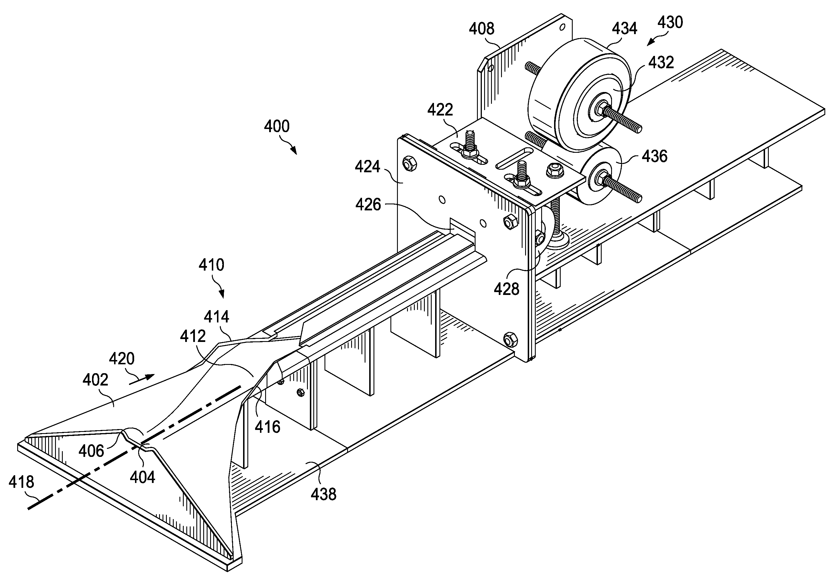
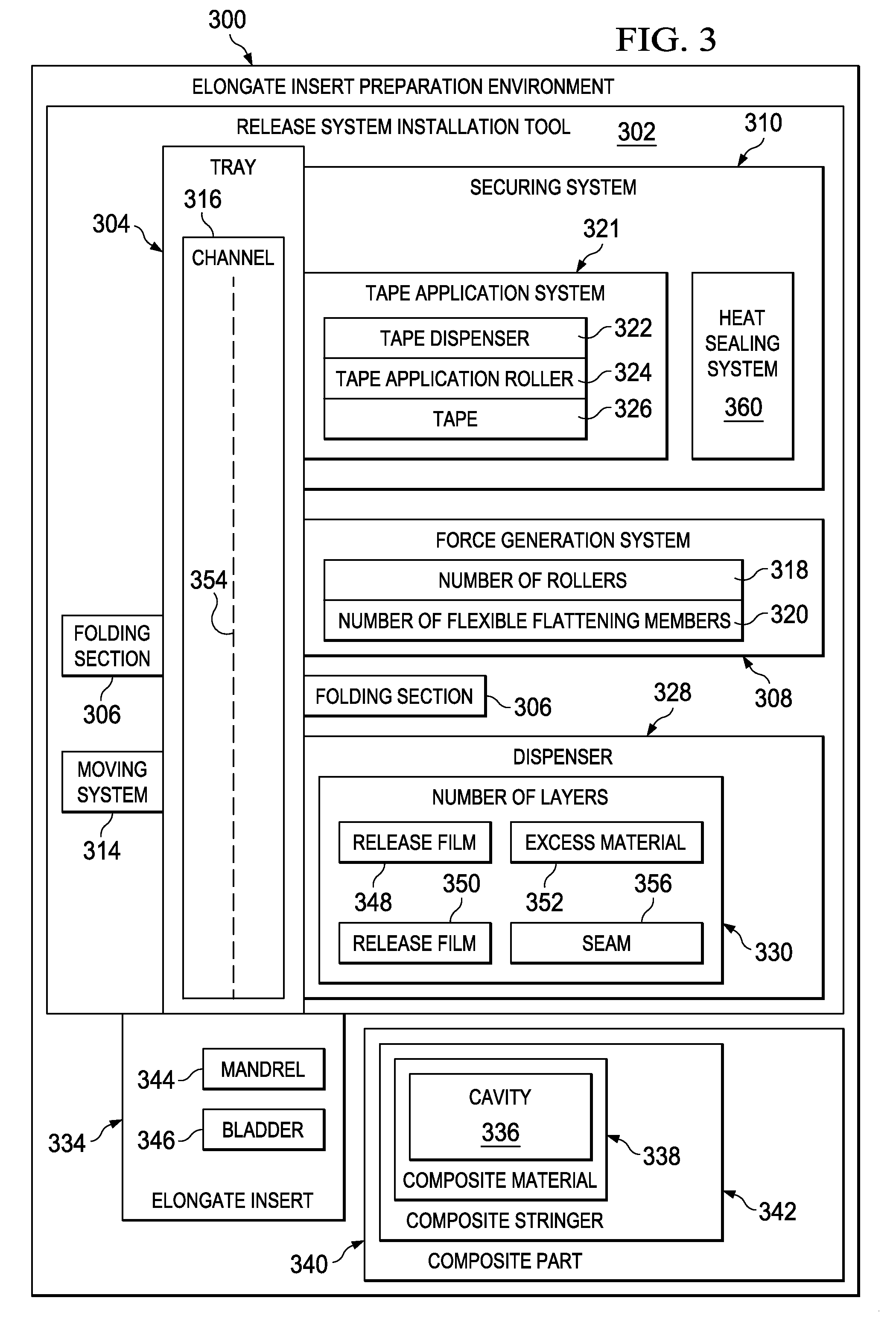
[0015]In yet another advantageous embodiment, a method is present for wrapping an elongate insert for a stringer with a number of layers for a release system. The elongate insert with a number of layers is moved in a channel in a tray through a folding section. The folding section folds the number of layers around the elongate insert. The elongate insert is moved in the channel with the number of layers folded over the elongate insert through a force generation system. The force generation system forces excess material towards a center line of the channel such that the number of layers is flattened. The elongate insert is moved in the channel with the number of layers flattened by the force generation system through a securing application system. The securing system secures the number of layers covering the elongate insert to form the release system.

Problems solved by technology

Further, composite materials may provide longer service life for various components in an aircraft.
This process may be time consuming.
Further, in some cases, the material wrapping the elongate insert may not be properly secured, secured too loosely, and / or have some other problem.
These issues may lead to problems with extracting the elongate insert from the cavity after curing of the composite part.
These situations may not be desirable.
Heat shrink materials, however, require the application of heat over the entire distance of the elongate insert.
When a rubber mandrel is used as the elongate insert, the heat shrink material also may distort the cross section of this type of elongate insert.

Method used


Image

  • Automated elongate insert wrapping system
  • Automated elongate insert wrapping system
  • Automated elongate insert wrapping system

Examples


Embodiment Construction

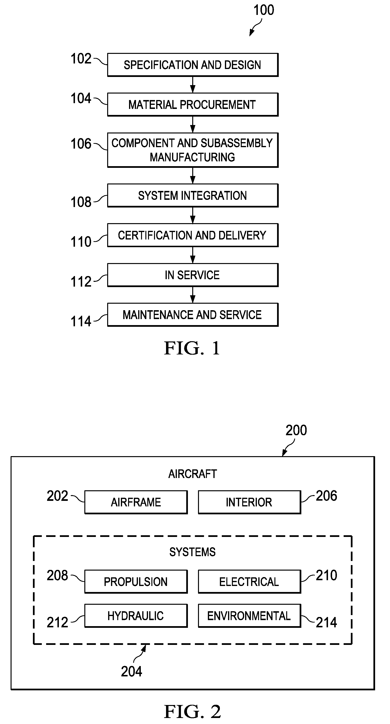
[0026]Referring more particularly to the drawings, embodiments of the disclosure may be described in the context of the aircraft manufacturing and service method 100 as shown in FIG. 1 and aircraft 200 as shown in FIG. 2. Turning first to FIG. 1, a diagram illustrating an aircraft manufacturing and service method is depicted in accordance with an advantageous embodiment. During pre-production, exemplary aircraft manufacturing and service method 100 may include specification and design 102 of aircraft 200 in FIG. 2 and material procurement 104.

[0027]During production, component and subassembly manufacturing 106 and system integration 108 of aircraft 200 in FIG. 2 takes place. Thereafter, aircraft 200 in FIG. 2 may go through certification and delivery 110 in order to be placed in service 112. While in service by a customer, aircraft 200 in FIG. 2 is scheduled for routine maintenance and service 114, which may include modification, reconfiguration, refurbishment, and other maintenance...


PUM

PropertyMeasurementUnit
lengthaaaaaaaaaa
lengthaaaaaaaaaa
flexibleaaaaaaaaaa

Abstract

A method and apparatus for a tray, a folding section connected to the tray, and a tape application system. The tray has a channel for receiving an elongate insert for a composite material with a number of layers for a release system. The folding section is capable of folding a number of layers around the elongate insert to cover the elongate insert as the elongate insert is moved through the folding unit. The tape application system is capable of applying a tape to the number of layers for covering the elongate insert to form the release system.

Description

BACKGROUND INFORMATION[0001]1. Field[0002]The present disclosure relates generally to manufacturing and, in particular, to manufacturing composite parts. Still more particularly, the present disclosure relates to a method and apparatus for preparing elongate inserts for use in manufacturing composite parts.[0003]2. Background[0004]Aircraft are being designed and manufactured with greater and greater percentages of composite materials. Some aircraft may have more than fifty percent of their primary structure made from composite materials. Composite materials may be used in aircraft to decrease the weight of the aircraft. This decreased weight may improve payload capacities and fuel efficiencies. Further, composite materials may provide longer service life for various components in an aircraft.[0005]Composite materials may be tough, light-weight materials, created by combining two or more dissimilar components. For example, a composite may include fibers and resins. The fibers and res...

Claims


Application Information

Patent Timeline
Patent Type & Authority Applications(United States)
IPC IPC(8): B29C65/00
CPCB29C65/5092Y10T156/1051B64C1/064B29C63/044B29C65/5042B29L2031/003B29C70/504B29C66/63B29C53/50Y10T156/1008Y10T156/101Y10T156/1011Y10T156/103Y10T156/1049B29C63/046B29C66/83411B29C66/1122B29C66/4332B29C66/8223
Inventor ROBINS, BRIAN G.JONES, DARRELL D.WILLDEN, KURTIS S.ROTTER, DANIEL M.
Owner THE BOEING CO
Why Eureka
Try Eureka