
Curved Dip Tube for Sprayer Heads

a spray bottle and tube technology, applied in the field of spray bottle, can solve the problems of tube pointing in the wrong direction, inability to use and difficulty in using all the contents of the spray bottl

Inactive Publication Date: 2010-06-24
SCHWANDT DARRELL J
View PDF28 Cites 8 Cited by
  • Summary
  • Abstract
  • Description
  • Claims
  • Application Information

AI Technical Summary

Benefits of technology

"The patent describes a curved dip tube that helps to dispense spray bottle contents without dry fire and allows the bottle to be tilted between 0 and 90 degrees while using all its contents. The patent also includes different drawings showing how to prepare the curved dip tube for different types of spray bottles. The technical effect of the patent is to provide a more efficient and effective spraying system that allows for continuous flow of spray and better utilization of the spray bottle contents."

Problems solved by technology

But when the bottle begins to empty, if the bottle is tipped downward or upward, the user experiences dry fire and it is difficult to use all the contents of spray bottles.
Unfortunately, for many end users the dip tube is pointing in the wrong direction.
Since many spray bottles are colored or opaque, instead of clear, the end user has no idea the dip tube is on the wrong side and it exasperates the problem of dry fire and the inability to use all the contents.
But many spray bottles are now designed with a bevel on the bottom and the weight or bobber can easily be caught on the wrong side of the bevel.
There are other limitations of flexible dip tubes integrated onto sprayer heads.
Also, the rubber material combined with the weight or bobber, have a higher cost then nylon or polyethylene dip tubes used in spray bottles.
Although it allows for the more common ridged or semi-ridged dip tube and helps eliminate dry fire; the change is to the bottle or mechanism and has increased the price of manufacturing the bottle.
These designs are much more complicated than standard sprayer heads as they incorporates multiple
Although this design does help eliminate dry fires and allows the user to spray inverted, these complex designs have a higher cost to manufacture and as a result tend to be offered as specialty sprayer heads.

Method used


Image

  • Curved Dip Tube for Sprayer Heads
  • Curved Dip Tube for Sprayer Heads
  • Curved Dip Tube for Sprayer Heads

Examples


first embodiment

FIG. 1, FIG. 2 and FIG. 3—First Embodiment

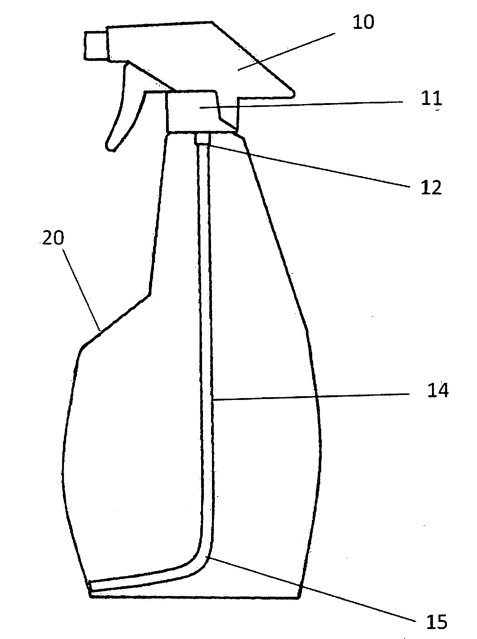
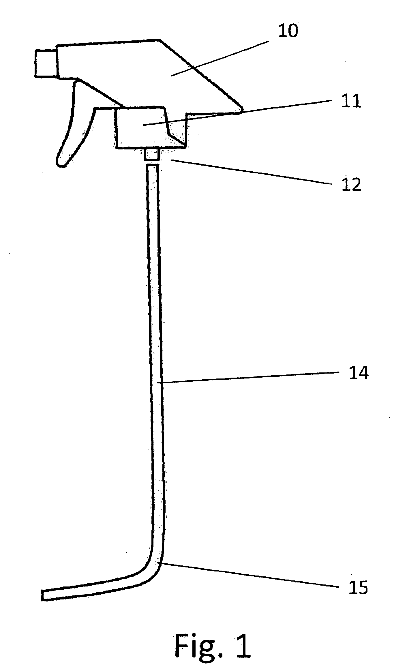
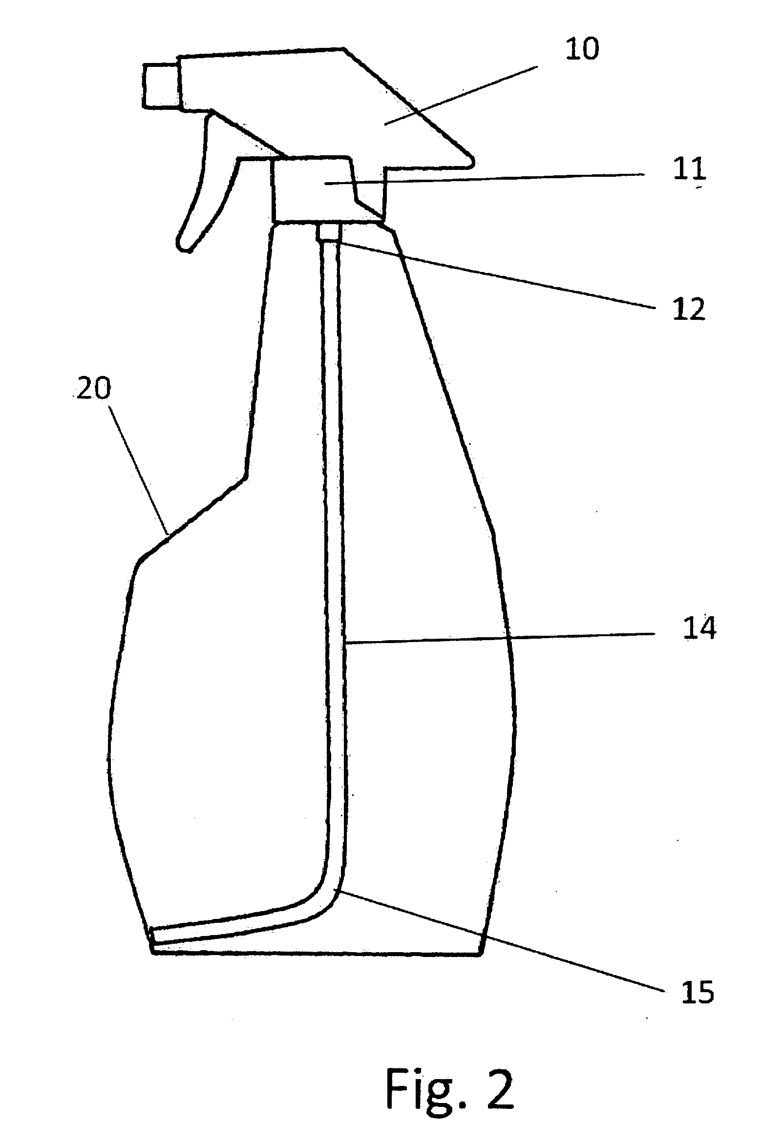
[0027]One embodiment of the curved dip tube is illustrated in FIG. 1, FIG. 2 and FIG. 3. FIG. 1 shows the curved dip tube 14 and a sprayer head 10. The sprayer head 10 is a 1.0 ml sprayer head—available through Unisan Products of Los Angeles, Calif. The relevant variations on sprayer heads related to this application are sealing cap size and dip tube connection size or integral dip tube. The sealing cap size 11 preferred by most sprayer head manufacturers is 28-400, although there are other sizes used in industry such as 28-410 and 28-415. The sealing cap size 11 need only fit the bottle 20 (FIG. 2) 21 (FIG. 3) to be used. The dip tube connections 12 size can vary. The curved dip tube 14 outer diameter need only match the inner diameter of the dip tube connection 12. Once matched the curved dip tube 14 can be inserted into the dip tube connection 12 beneath the sealing cap 11. The preferred material for the curved dip tube 14 is nylon or pol...


PUM


Abstract

A curved dip tube for sprayer heads that solves the problem of spraying air as a container's contents are dispensed and reduced to a level that allows the tip of a straight dip tube to become disengaged with the liquid as the container is tilted downward. As the user of a sprayer head tilts or tips it from a vertical to a horizontal position to spray the intended target the liquid level pools at the lowest point in the container. It then becomes advantageous for the tip of the curved dip tube to be positioned on the lowest point where the bottom meets the wall. This is accomplished by lengthening the dip tube and then curving it to direct the tip toward the side. Once installed onto a sprayer head and inserted into a container the curved dip tube extends toward the bottom of the container, curves and follows the contour of the bottom of the container, pointing in the same direction as the sprayer head output nozzle. The liquid contents of the container can now be fully consumed without spraying air during operation as the consumer uses the product in its entirety.

Description

CROSS-REFERENCE TO RELATED APPLICATIONS[0001]This application claims the benefits of provisional patent application serial number 61138801 filed Jan. 5, 2009 by the present inventor.FEDERALLY SPONSORED RESEARCH[0002]Not applicableSEQUENCE LISTING OR PROGRAM[0003]Not applicableBACKGROUND[0004]1. Field[0005]This application relates to sprayer heads, specifically to the design of the dip tube used to pick up the contents of spray bottles.[0006]2. Prior Art[0007]For the purpose of clarity in this application the term “dry fire” is defined as: When a spray bottle still contains liquid but the dip tube extending from the sprayer head becomes disengaged with the liquid and the sprayer head pumps air instead of liquid.[0008]The prior art can be broken up into 4 groups. Common sprayer heads, designs using flexible dip tubes, designs deflecting the dip tube to a corner of the bottle and designs in which the sprayer head is redesigned to allow inverted spraying.[0009]Currently common sprayer h...

Claims


Application Information

Patent Timeline
Patent Type & Authority Applications(United States)
IPC IPC(8): B67D5/12
CPCB05B11/0059B05B15/005B05B11/3057B05B15/30B05B11/1057
Inventor SCHWANDT, DARRELL J.
Owner SCHWANDT DARRELL J
Learn More