Mesh stacking chair

a stacking chair and mesh technology, applied in the field of mesh stacking chairs, can solve the problems of affecting the quality of the finished product, the difficulty of handling or storage of stacked chairs, and the tendency of chairs on the end of the hanger to fall, etc., and achieves the effects of easy and quick assembly, high density storage, and great comfor

Active Publication Date: 2010-06-24
MITY-LITE
View PDF124 Cites 13 Cited by
  • Summary
  • Abstract
  • Description
  • Claims
  • Application Information

AI Technical Summary

Benefits of technology

[0015]It has been recognized that it would be advantageous to develop a chair with greater comfort while maintaining high density storage and providing for stackability. In addition, it has been recognized that it would be advantageous to develop a chair utilizing a mesh seating surface for comfort and space saving in a stacked configuration. In addition, it has been recognized that it would be advantageous to develop a chair utilizing the comfort of ...

Problems solved by technology

It will be appreciated that numerous stacked chairs can be difficult to handle or store, and may separate from one another.
Furthermore, it will be appreciated that chairs can be unsymmetrical so that stacking several chairs together results in a non-linear stack which can lead to separation.
Other prior art folding chairs have complicated and expensive hanging rack systems.
One disadvantage of these types of systems is that chairs on the end of the hangers tend to fall off the rack, and the wheeled racks are difficult to move and maneuver.
Typical prior art chairs can have rigid metal seats and seat...

Method used


Image

  • Mesh stacking chair
  • Mesh stacking chair
  • Mesh stacking chair

Examples


Embodiment Construction

)

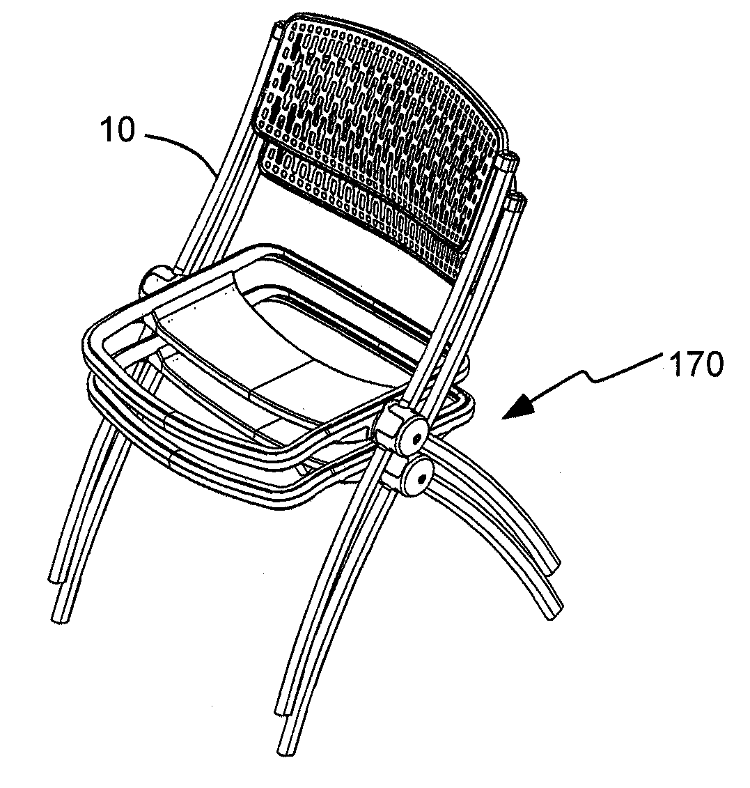
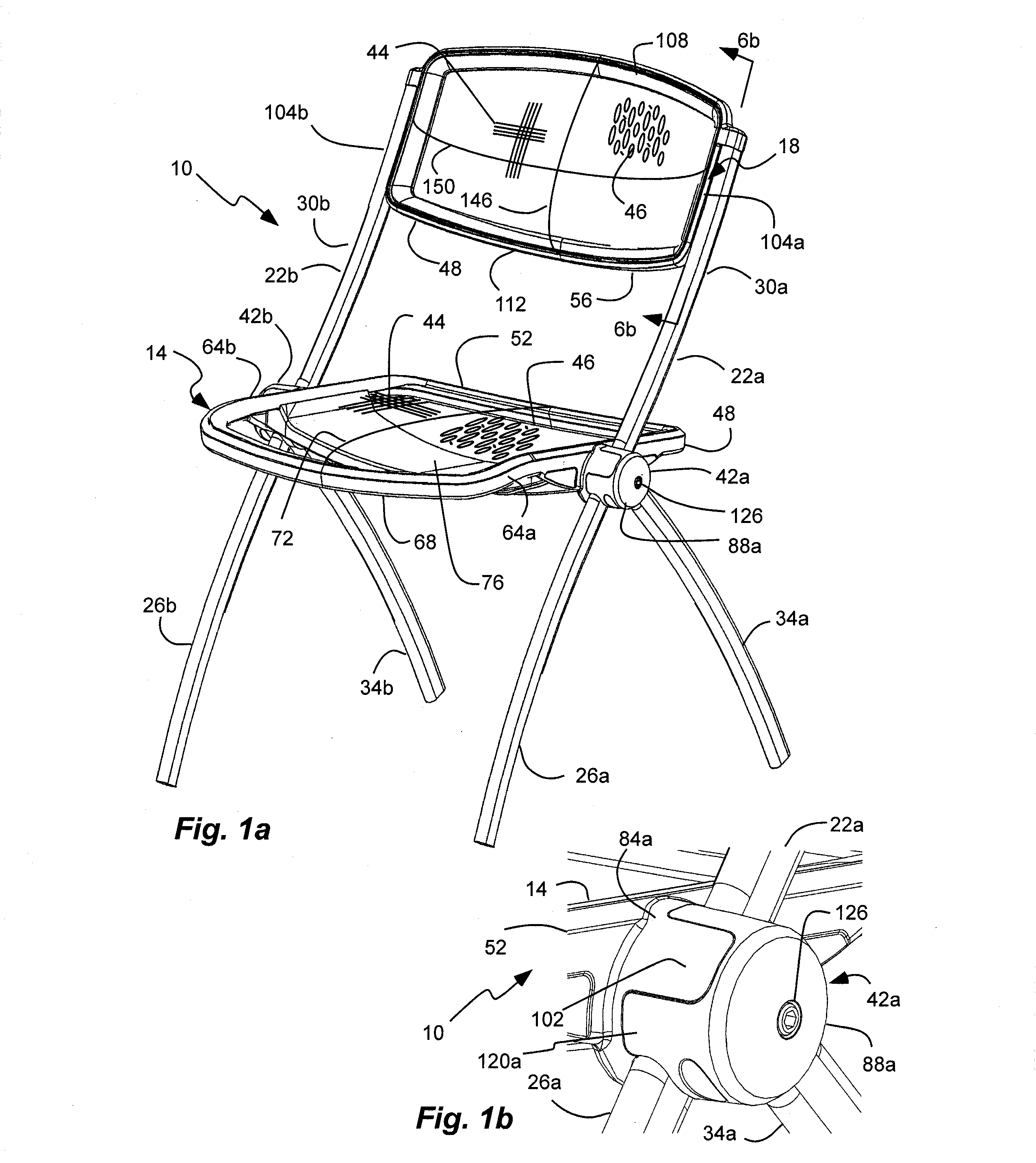
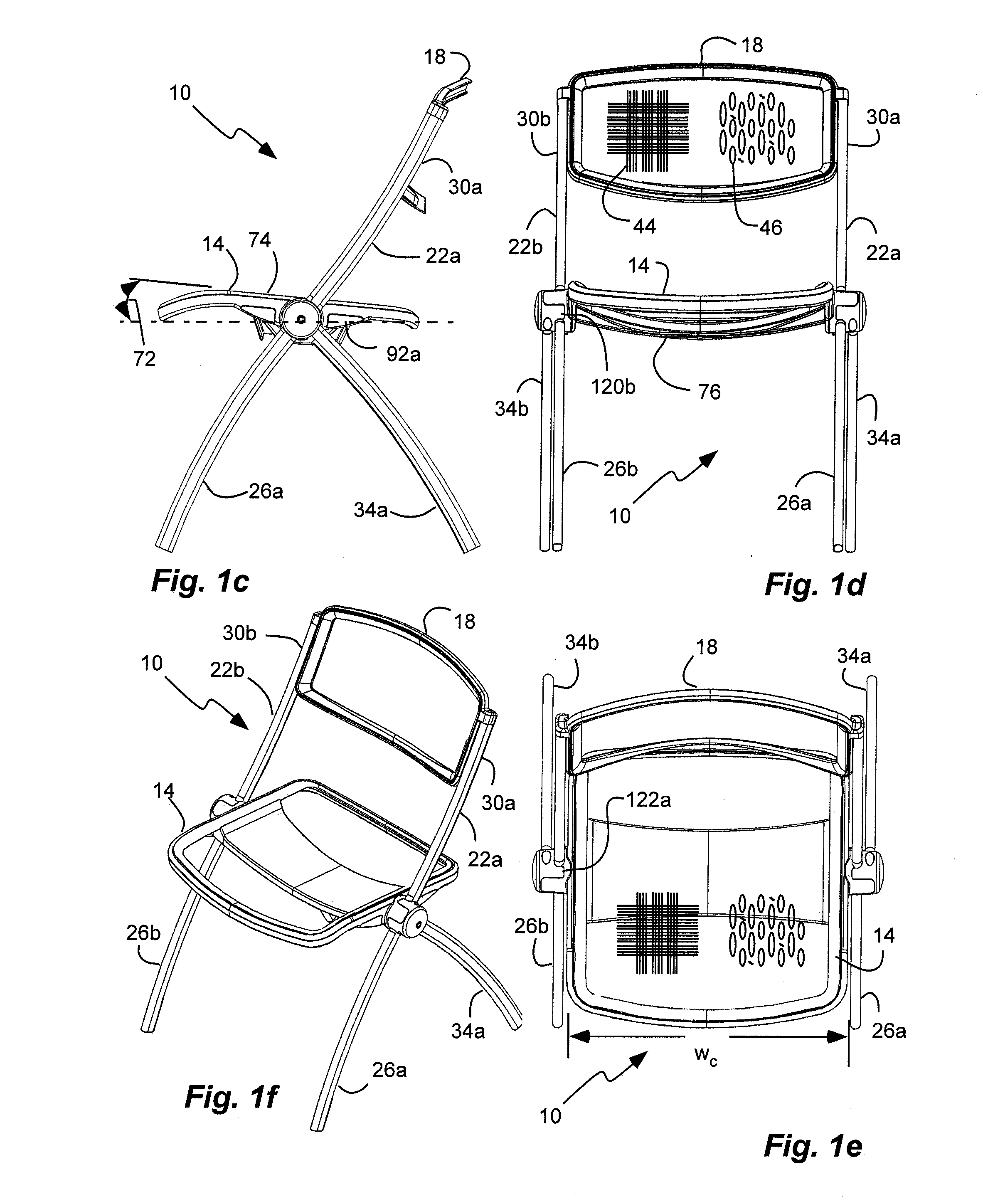
[0070]As illustrated in FIGS. 1a-h, a stacking chair, indicated generally at 10, with a seat 14 and a backrest 18 is shown in an example implementation in accordance with the invention. Such a stacking chair can be utilized by institutions or residentially. The seat 14 and backrest 18 can have a stretched mesh over all-plastic frames or hoops to achieve upholstered comfort in a non-upholstered stacking chair. In addition, the chair can use the all-plastic frames with mesh for the seat and the backrest supported by a metal frame and legs for a sturdy, strong, and light-weight chair. In addition, the metal frame and / or legs can be secured to the seat hoop by a joint where the front and rear legs overlap. The chair, or its components, can be shipped in a flat, knock-down box and can be ready to assemble (RTA). The chair can be easily and quickly assembled by placing the legs in the joint and attaching an outer clamp of the joint and snap fitting the backrest. The chair, or its compone...


PUM

PropertyMeasurementUnit
Distanceaaaaaaaaaa
Elastomericaaaaaaaaaa
Flexibilityaaaaaaaaaa

Abstract

A stackable chair has a seat and a backrest carried between opposite frame sides each with a backrest support, a front leg and a rear leg. One or both of the seat and the backrest have a continuous sheet of flexible and elastic mesh or patterned open texture plastic held across and substantially covering an opening in an all-plastic hoop fixed between the frame sides.

Description

PRIORITY CLAIM[0001]Priority is claimed to copending U.S. Provisional Patent Application Ser. No. 61 / 168,837, filed Apr. 13, 2009, which is hereby incorporated herein by reference in its entirety.[0002]Priority is claimed to copending U.S. Provisional Patent Application Ser. No. 61 / 140,756, filed Dec. 24, 2008, which is hereby incorporated herein by reference in its entirety.[0003]This is a continuation-in-part of U.S. patent application Ser. Nos. 12 / 422,792; 12 / 422,801; 12 / 422,811; and 12 / 422,821; all filed Apr. 13, 2009, and which all claim priority to U.S. Provisional Patent Application Ser. No. 61 / 140,756, filed Dec. 24, 2008, and which all are hereby incorporated herein by reference in their entirety.CROSS-REFERENCE TO RELATED APPLICATIONS[0004]U.S. patent application Ser. No. ______, filed Nov. 4, 2009, as TNW Docket No. 00538-32702.NP.B and entitled “Clamping Joint for Chair” which is hereby incorporated herein by reference in its entirety.[0005]U.S. Design patent application...

Claims


Application Information

Patent Timeline
IPC IPC(8): A47C3/04A47C7/54A47C5/12
CPCA47C1/124A47C3/04A47C7/543A47C7/54A47C7/282
Inventor SMITH, RICHARD D.
Owner MITY-LITE
Why Eureka
Try Eureka