Video projector

a projector and video technology, applied in the field of video projectors, can solve problems such as the b>102/b> susceptible to damage of the projection lens, and achieve the effect of avoiding damage to the projection lens and not reducing interior spa

Inactive Publication Date: 2010-06-24
SANYO ELECTRIC CO LTD
View PDF4 Cites 3 Cited by
  • Summary
  • Abstract
  • Description
  • Claims
  • Application Information

AI Technical Summary

Benefits of technology

[0007]It is an object of the present invention to provide a video projector that avoids damaging of the projection lens when the projector is carried, while including a carrying handle that does not reduce interior space in the housing that is used to accommodate devices.

Problems solved by technology

As a result, the projection lens 102 is susceptible to being damaged when the projector is being carried.

Method used


Image

  • Video projector
  • Video projector
  • Video projector

Examples


Embodiment Construction

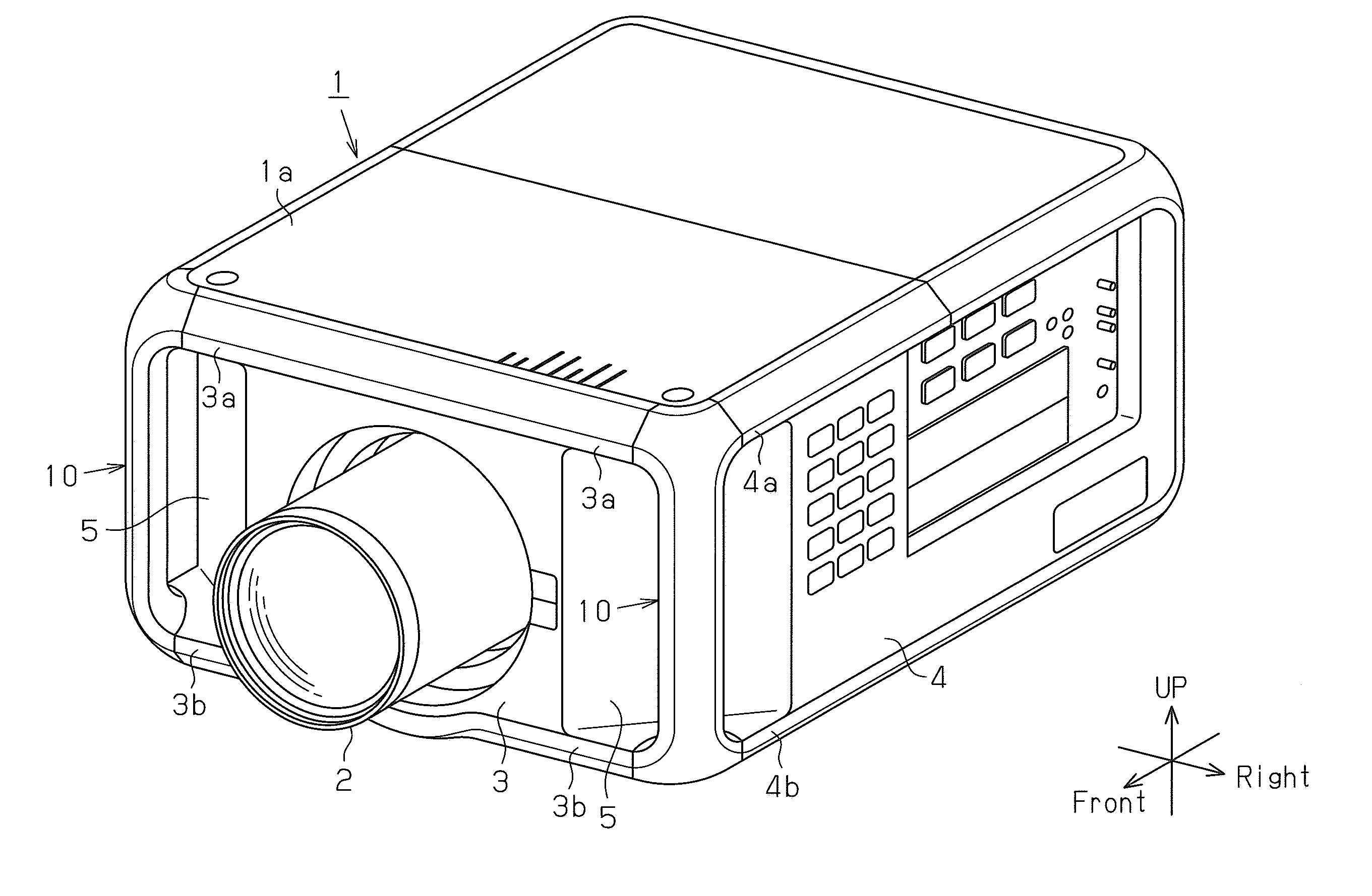
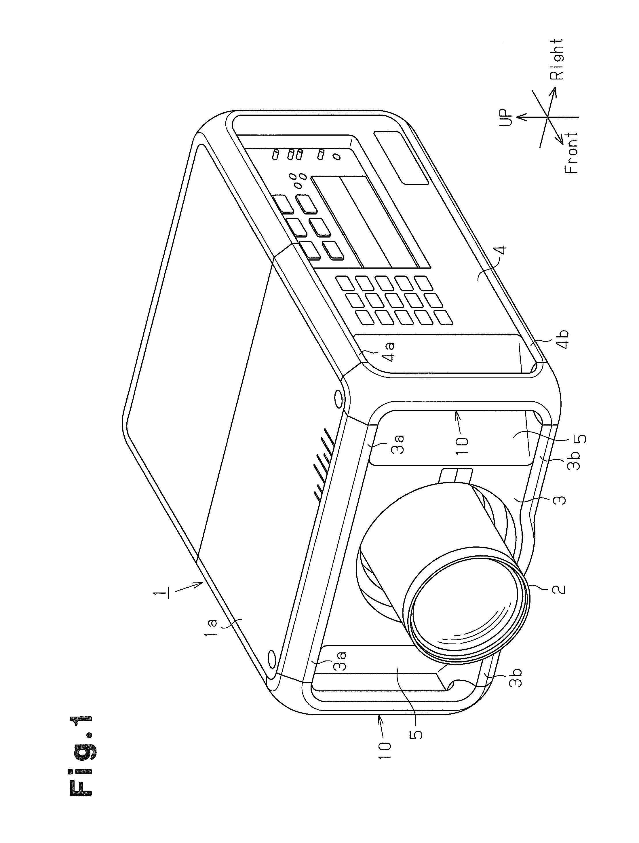
[0019]In this specification, the terms “front surface” and “front wall” refer to the surface of a video projector on which a projection lens is arranged (refer to FIG. 1). The frame of reference for the terms “up” and “down” is a state in which the projector is horizontally set. A projector is normally set so that its largest surface faces downward.

[0020]A video projector according to one embodiment of the present invention will now be discussed. As shown in FIG. 1, the video projector includes a housing 1, which houses optical devices and electronic components, and a projection lens 2, which projects outward from a middle part of a front wall 3 of the housing 1. A carrying handle 10 may be arranged in one or both of left and right edges of the front wall 3 of the housing 1.

[0021]In the illustrated example, the housing 1 is a substantially rectangular cuboid including portions formed by chamfering edges, which connect adjacent sides. More specifically, the housing 1, the height of w...


PUM


Abstract

A video projector has a housing, with front and side walls, and a projection lens arranged in the front wall. A carrying handle is fastened to the housing to allow the video projector to be hand carried. The housing includes a sloped wall formed between at least one of the side walls and the front wall. The sloped wall extends diagonally relative to the front wall and at least one of the side walls. The carrying handle has a grip extending along a hypothetical intersecting line of an extended plane of the front wall and an extended plane of at least one of the side walls. The carrying handle and the sloped wall define an opening into which the hand of a person gripping the carrying handle is insertable.

Description

CROSS-REFERENCE TO RELATED APPLICATIONS[0001]This application is based upon and claims the benefit of priority from prior Japanese Patent Application No. 2008-326248, filed on Dec. 22, 2008, the entire contents of which are incorporated herein by reference.BACKGROUND OF THE INVENTION[0002]The present invention relates to a video projector, and more particularly, to a video projector including a carrying handle.[0003]A projector modulates light, which is emitted from a light source, in accordance with light information to form an optical image. The projector then enlarges and displays the optical image on a large screen. Such a projector includes a housing, which houses optical devices, such as the projection lens, and electronic components. The housing of the projector is typically a substantially rectangular cuboid, the height of which is less than either the width or length.[0004]To reduce the size of the substantially rectangular cuboid housing, the projection lens is arranged in...

Claims


Application Information

Patent Timeline
Patent Type & Authority Applications(United States)
IPC IPC(8): H04N5/64
CPCG03B21/00G03B21/005
Inventor SUZUKI, SOSHIN, BUMJIN
Owner SANYO ELECTRIC CO LTD
Why Eureka
Try Eureka