Toolholder and Toolholder Assembly with Elongated Seating pads

Active Publication Date: 2010-06-24
KENNAMETAL INC
View PDF25 Cites 49 Cited by
  • Summary
  • Abstract
  • Description
  • Claims
  • Application Information

AI Technical Summary

Benefits of technology

[0006]One embodiment of the invention is directed to a toolholder for use in a metalworking operation, wherein the toolholder is adapted to hold an on-edge cutting insert with a depth and having first and second opposing segments about a central plane and with a central axis therethrough. Each segment of the insert has at least three sides and associated corners defining end cutting edges and, wherein each segment is radially offset relative to the other. The toolholder has a body extending along a longitudinal axis and having a first end and a pocket extending into the first end, wherein the pocket has at least two sides and the general shape and depth of the cutting insert intended to be held therein and, wherein the at least two sides intersect to define a poc

Problems solved by technology

However, as illustrated in U.S. Pat. No. 3,490,117, which illustrates on-edge cutting inserts mounted within the pockets of a toolholder, a unique problem arises.
While this provides adequate clearance for th

Method used


Image

  • Toolholder and Toolholder Assembly with Elongated Seating pads
  • Toolholder and Toolholder Assembly with Elongated Seating pads
  • Toolholder and Toolholder Assembly with Elongated Seating pads

Examples


Embodiment Construction

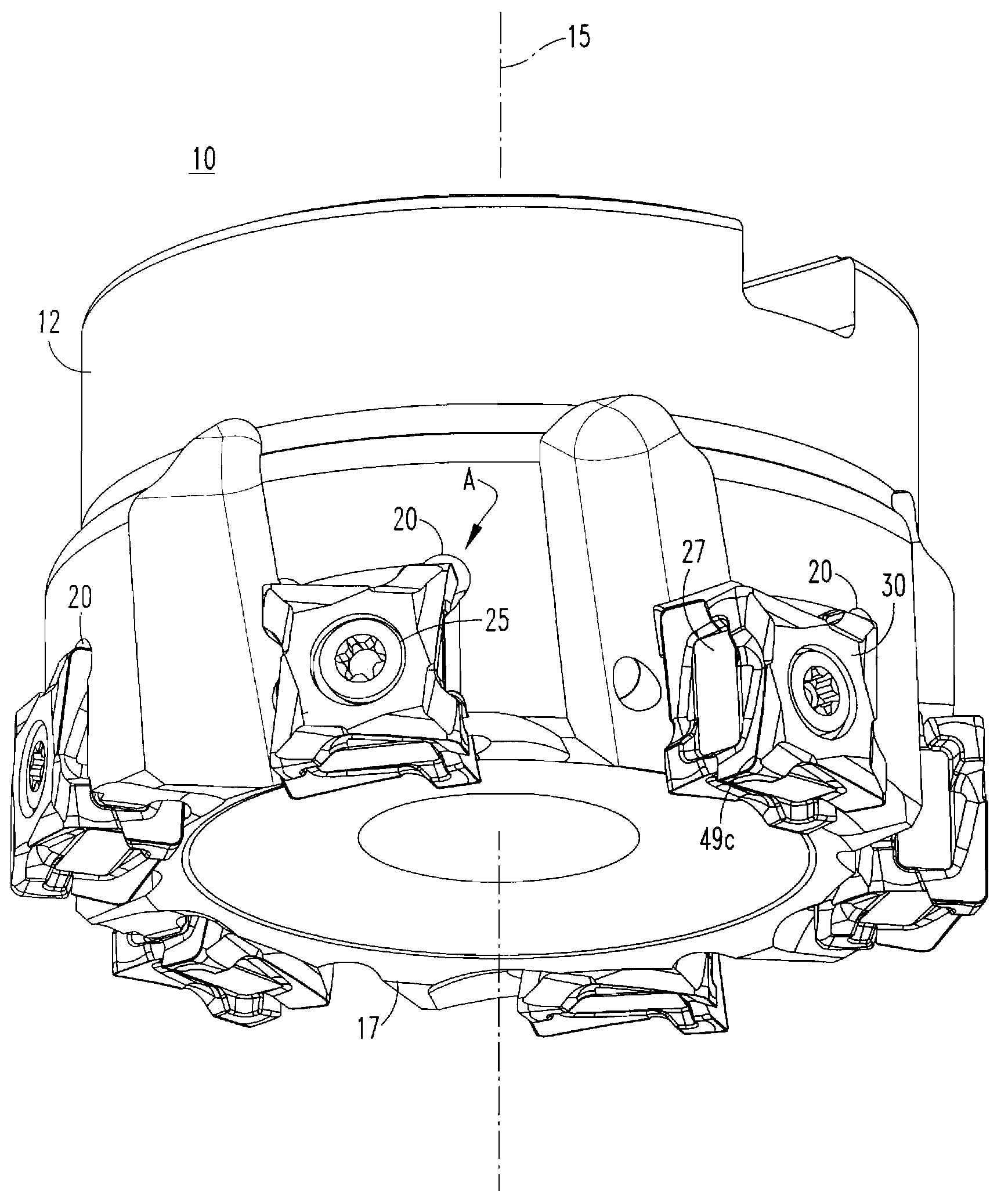
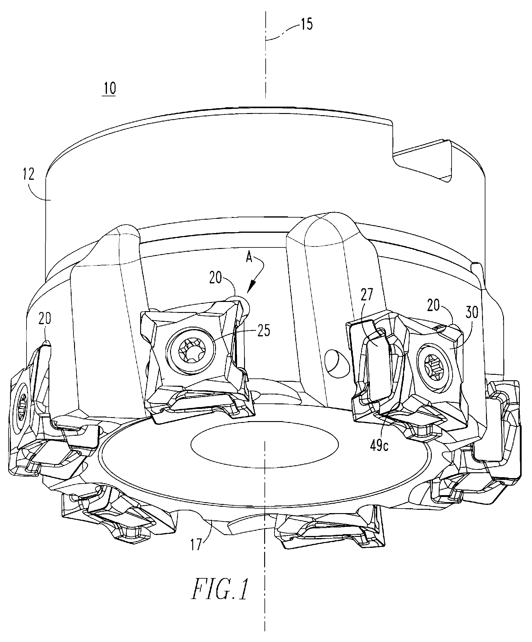
[0017]FIG. 1 illustrates a toolholder 10 having a body 12 extending along a longitudinal axis 15 and having a first end 17. A plurality of pockets 20 extend about the perimeter of the toolholder body 12 and mounted within each of these pockets 20 is a cutting insert 25. The cutting insert 25 is an on-edge cutting insert, whereby the major cutting edges are located on the ends 27, as opposed to the sides 30 of the cutting insert 25. For on-edge cutting inserts, the surface area of each side is significantly greater than the surface area of any one of the ends 27.

[0018]Although some milling cutters may have different types of cutting inserts mounted within different pockets, for the purposes of discussion and as illustrated herein, all of the cutting inserts 25 are identical and the pockets 20 are identical, such that only a single cutting insert 25 and single pocket 20 will be discussed with the understanding that the others are identical.

[0019]Directing attention to FIG. 3, a typica...


PUM

PropertyMeasurementUnit
Fractionaaaaaaaaaa
Angleaaaaaaaaaa
Angleaaaaaaaaaa

Abstract

A toolholder has a pocket adapted to receive a double-sided on-edge cutting insert, wherein the corners of each side of the insert are radially shifted with respect to one another and has mounting pads preferably mounted about the sides of the cutting insert. The relief area for the corners of the insert is selectively fabricated to maximize the length of the support pads within the pocket of the toolholder.

Description

BACKGROUND OF THE INVENTION[0001]1. Field of the Invention[0002]This invention relates to toolholders for metal working operations and, more specifically, to a toolholder having a pocket with elongated seating pads for accommodating matching seating pads of a cutting insert mounted within the pocket.[0003]2. Description of Related Art[0004]A goal of most metal working operations is to perform a given machining task in the least amount of time and in a manner that will not result in premature tool failure. In particular, in a milling operation using on-edge cutting inserts within pockets of a milling cutter, it is necessary to securely mount these inserts within the pockets. Typically, such on-edge inserts include side surfaces which contact seating pads within the pocket for support. However, as illustrated in U.S. Pat. No. 3,490,117, which illustrates on-edge cutting inserts mounted within the pockets of a toolholder, a unique problem arises. To provide a reversible cutting insert ...

Claims


Application Information

Patent Timeline
IPC IPC(8): B23B27/16
CPCB23B2205/12B23C5/006B23C5/2204B23C2200/367Y10T407/192B23B2200/3681Y10T407/2272Y10T407/23Y10T407/2276B23C2210/168B23C5/2213
Inventor SPITZENBERGER, KONRADCRAIG, KAREN A.CHERLA, SRINIVAS
Owner KENNAMETAL INC
Why Eureka
Try Eureka