[0006]An object of the present invention, which is constituted to solve this problem, is to provide a stage apparatus that makes it possible to move the movable body, which is the wafer stage, without generating pitching.
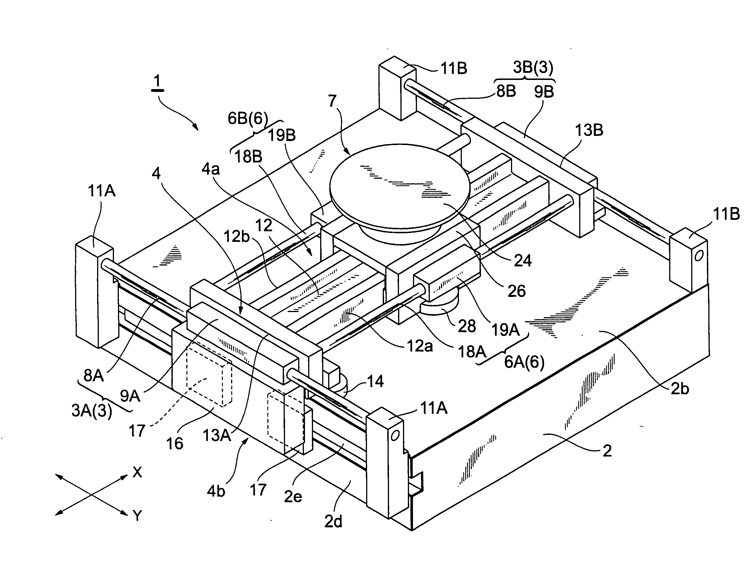
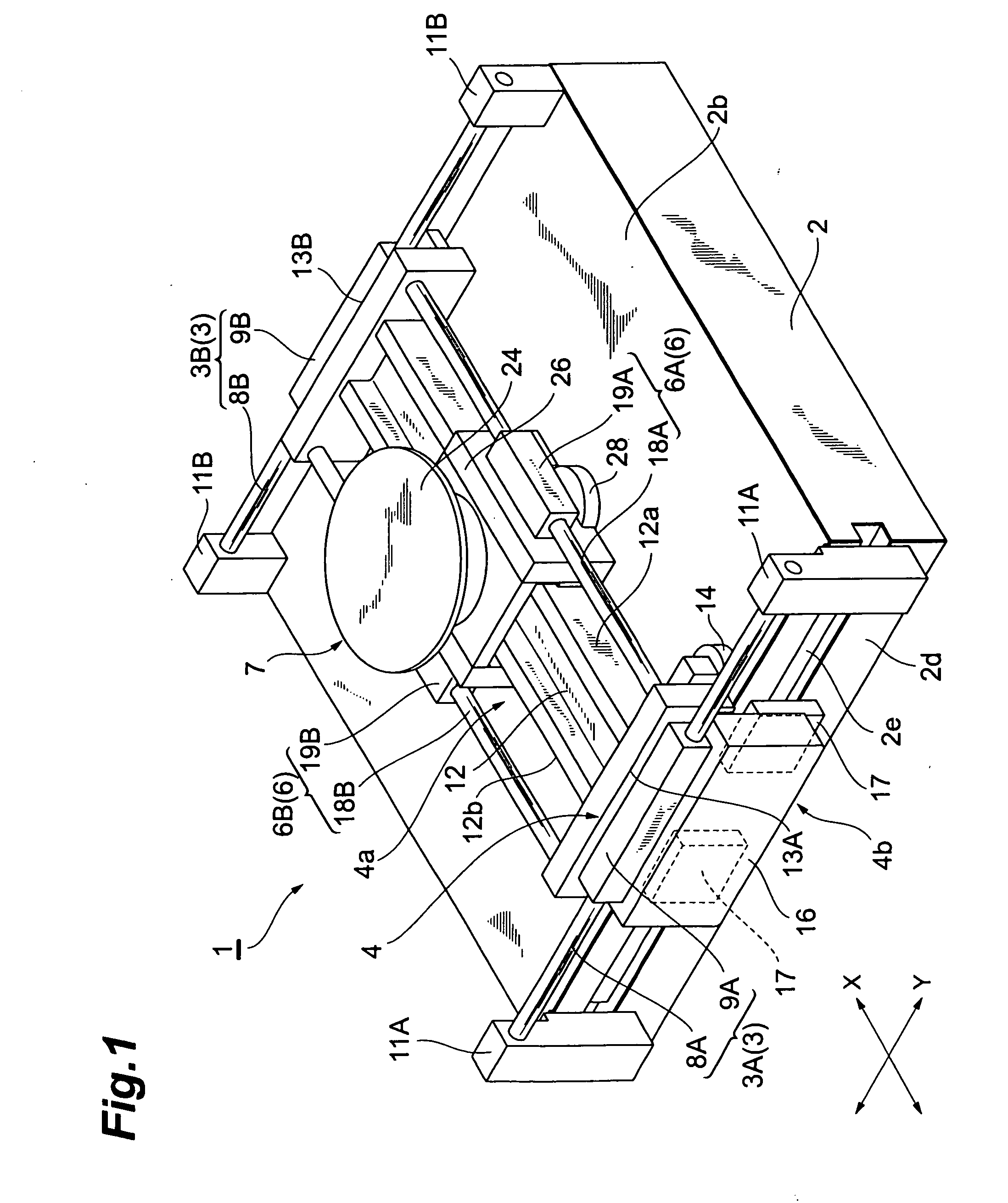
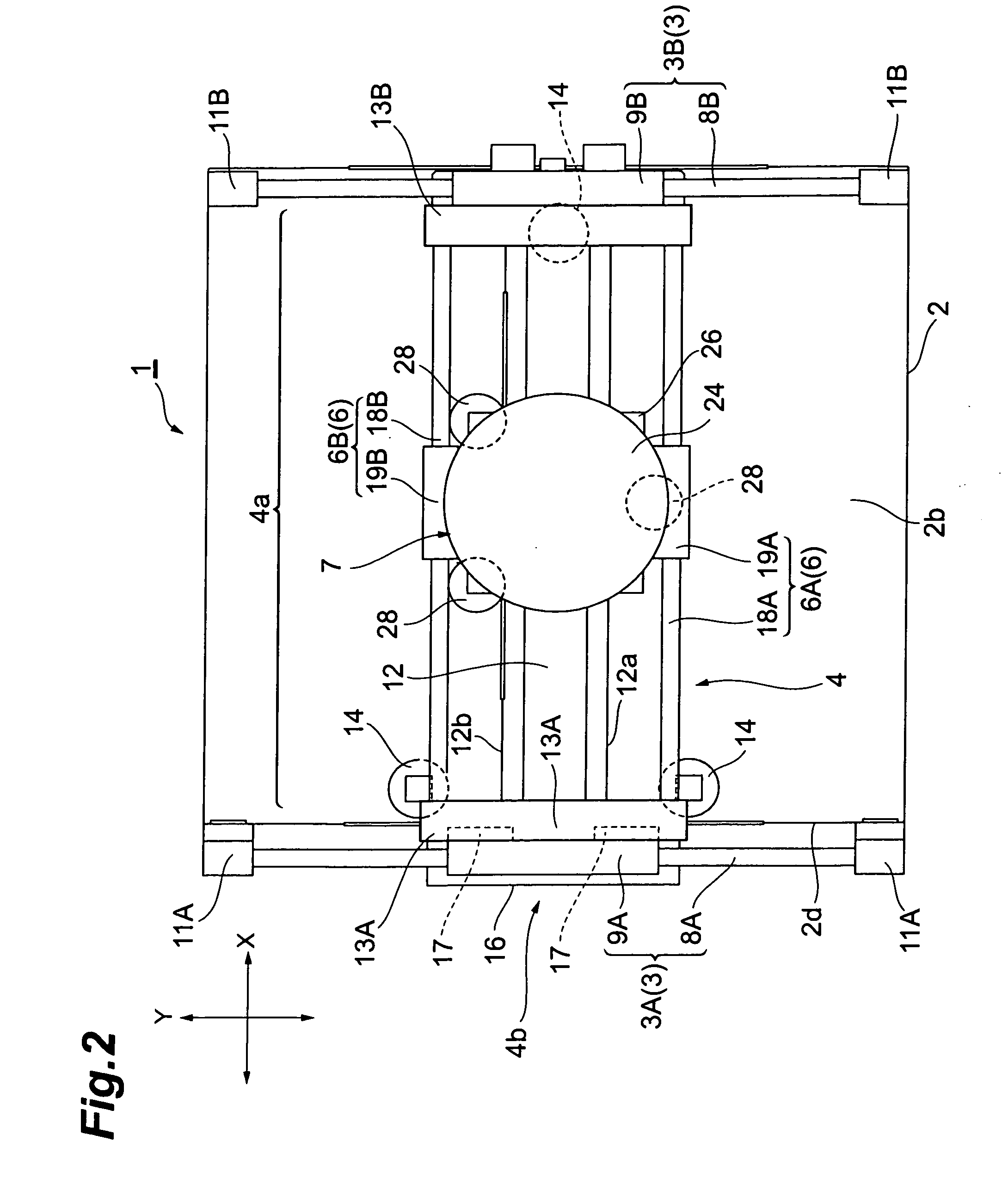
[0007]A stage apparatus related to the present invention has a pair of Y-axis stators, which are fixed to the top surface of a base and extend in the Y-axis direction, a pair of Y-axis movers that move along the respective Y-axis stators, a shaft motor having an X-axis shaft, which extends in an X-axis direction that is orthogonal to the Y-axis direction and is connected to the pair of Y-axis movers, and an X-axis mover, which is constituted by a coil that surrounds this X-axis shaft, and a movable body that moves over the base, and is characterized in that the X-axis mover is connected to the side of the movable body. According to a stage apparatus like this, since the X-axis mover is arranged on the side of the movable body, it is possible to lower the location of the movable body downwardly in the vertical direction compared to the prior art, wherein the movable body rests atop the X-axis mover, making it possible to bring the center of gravity location of the movable body closer to the height location of the shaft motor having the X-axis shaft and the X-axis mover. Consequently, the movable body can be stabilized and supported by the shaft motor, making it possible to move the movable body without generating pitching. Further, since the X-axis mover is disposed on the inside directly beneath a table in the prior art, the X-axis mover comes into close proximity to the location of the wafer at times and adversely affects this wafer by making it easier for heat to be transferred to sites that demand precision. Further, disposing the X-axis mover inside also increases the risk of heat buildup. By contrast, according to the stage apparatus related to the present invention, providing the X-axis mover on the side of the movable body makes it possible to distance the X-axis mover from the wafer location, enabling a constitution in which there is no heat buildup.
[0008]Further, it is preferable that the shaft motor be provided in a pair, and that the pair of shaft motors be respectively arranged on both outer sides of the movable body. Consequently, it is possible to stably move the movable body in accordance with applying thrust from both outer sides of the movable body.
[0009]Further, it is preferable that the stage apparatus of the present invention have a guidebeam, which is connected to the pair of Y-axis movers, is positioned on the inner side of the movable body, and extends in the X-axis direction, and that the movable body have a lateral part, which faces the side of the guidebeam, and a pair of first air bearings, which are disposed on the lateral part, and blow air on the side of the guidebeam. Consequently, since the X-axis shaft and X-axis mover are respectively arranged on the outer side of the lateral part of the movable body, the movable body can be made smaller and lighter weight than when the X-axis shaft and X-axis mover are arranged in the inner side of the movable body.
[0010]Further, it is preferable that the movable body have a second
air bearing that blows air on the top surface of the base. Consequently, the top surface of the base can be treated as a gliding surface, making it possible to move the movable body while supporting same in a non-contact state. Furthermore, the
air bearing not only blows air, but can also have a suction function.
[0011]Further, it is preferable that the height of the center of gravity of the movable body coincide with the heights of the center of the shafts of the X-axis shaft and X-axis mover. Consequently, it is possible to further stabilize and support the movable body with the X-axis drive part, making it possible to move the movable body without generating pitching.

