Radio Communication Device and Radio Communication Method

Active Publication Date: 2010-06-24
KYOCERA CORP
View PDF3 Cites 13 Cited by
  • Summary
  • Abstract
  • Description
  • Claims
  • Application Information

AI Technical Summary

Benefits of technology

[0041]According to the aspects of the present invention, a radio communication device and a radio communication method can be provided that can suppress degradation of communication quality even when a state of a propagat

Problems solved by technology

Thus, there is a problem of degrading the communication quality of radio signals received by the radio communication terminal.
Specifically, when the radio communication terminal or the object existing around the radio communication terminal moves at hi

Method used


Image

  • Radio Communication Device and Radio Communication Method
  • Radio Communication Device and Radio Communication Method
  • Radio Communication Device and Radio Communication Method

Examples


Example

First Embodiment of the Present Invention

(Overall Schematic Configuration of Mobile Communication System According to First Embodiment)

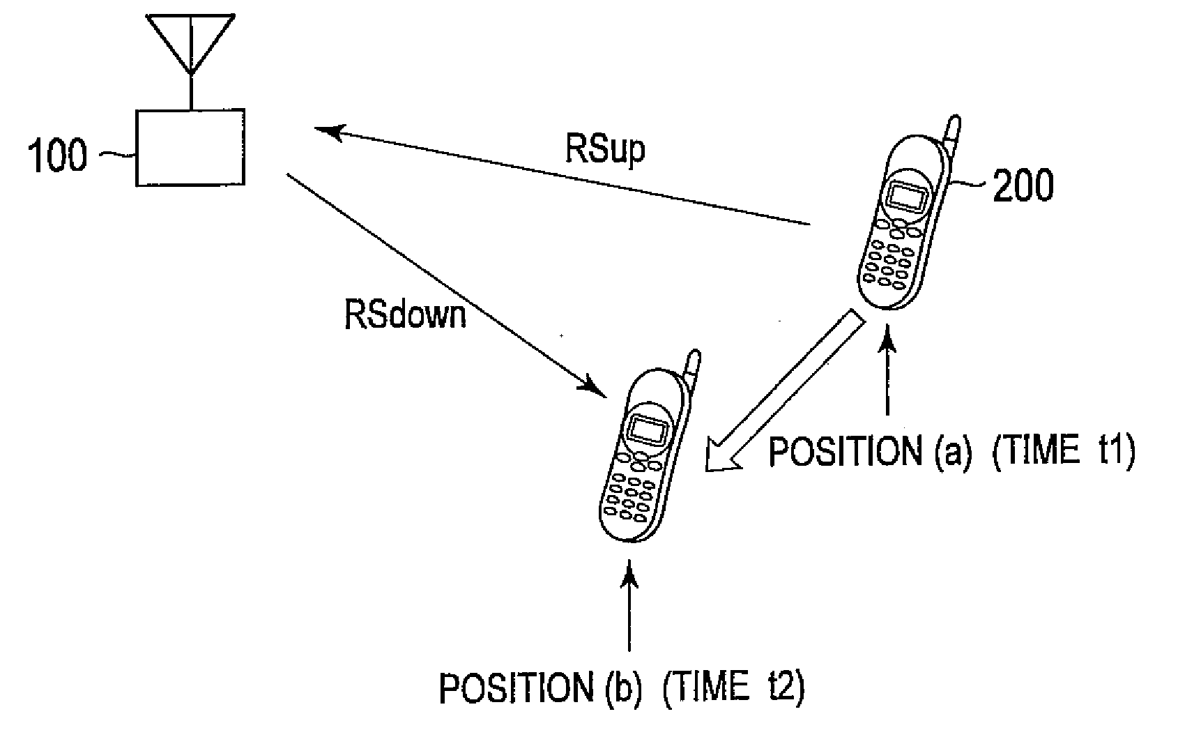
[0056]FIG. 1 is an overall schematic configuration diagram of a mobile communication system including a radio communication device according to the present embodiment. The mobile communication system is provided with a radio base station 100 (radio communication device) and a radio communication terminal 200 (counterpart radio communication device). Note that the number of the radio base stations and the radio communication terminals configuring the mobile communication system is not limited to the number shown in FIG. 1.

[0057]In the mobile communication system, radio communications are performed between the radio base station 100 and the radio communication terminal 200. The mobile communication system is a mobile communication system that uses Time Division Multiple Access / Time Division Duplex (TDMA / TDD).

[0058]The radio communication terminal 200 i...

Example

Second Embodiment of the Present Invention

[0134]For a configuration of a radio base station 100 according to a second embodiment of the present invention, differences from the first embodiment described above will be described hereinafter. In the following, parts different from the radio base station 100 of the first embodiment will be mainly described and description of similar functions will be omitted as appropriate.

(Configuration of Radio Base Station 100 According to Second Embodiment)

[0135]In the present embodiment, in the radio base station 100 according to the first embodiment, the radio base station 100 according to the present embodiment further includes an antenna selector 131, as shown in FIG. 10.

[0136]The antenna selector 131 is connected to a desired wave power calculator 107 and an adaptive processing controller 113. The antenna selector 131 selects at least any of element antennas 101_1 to 101—n on the basis of a state of a received radio signal. Specifically, on the...

Example

(Configuration of Radio Base Station 100 According to Third Embodiment)

[0144]In the radio base station 100 according to the present embodiment, an uplink signal RSup and a downlink signal RSdown to be transmitted / received to / from the radio communication terminal 200 use a plurality of frequency bands.

[0145]In addition, as shown in FIG. 12, the radio base station 100 according to the present embodiment further includes adaptive controllers 151_1 to 151_3, a propagation path fluctuation correlation value calculator 152, and a grouping unit 153, when compared with the radio base station 100 according to the first embodiment. Note that, although the case in which the radio base station 100 according to the present embodiment includes three adaptive controllers 151_1 to 151_3 is described as an example, the number shall not be limited to this.

[0146]The propagation path correlation value calculator 152 is connected to a Doppler identifier 104 and a grouping unit 153. The propagation path ...


PUM


Abstract

A radio communication device according to the present invention is a radio communication device which adaptively controls directivity of transmission radio signals by use of a plurality of element antennas on the basis of received radio signals received from a counterpart radio communication device that is a communication target radio communication device, the transmission radio signals being to be transmitted to the counterpart radio communication device, the radio communication device comprising: a propagation path state detector configured to detect a fluctuation state of a propagation path to the counterpart radio communication device on the basis of the received radio signal; and a transmission controller configured to control a phase of the transmission radio signal on the basis of the fluctuation state of the propagation path detected by the propagation path state detector.

Description

TECHNICAL FIELD[0001]The present invention relates to a radio communication device and a radio communication method in which directivity of radio signals to be transmitted to a communication target radio communication device is adaptively controlled by use of a plurality of element antennas on the basis of radio signals received from the communication target radio communication device.BACKGROUND ART[0002]Conventionally, in a radio communication system such as a mobile communication system, there has been widely used adaptive array control that adaptively controls directivity of radio signals by using a plurality of element antennas, the radio signals being to be transmitted from a radio base station to a communication target radio communication device, for example, a radio communication terminal. With the adaptive array control, directivity of radio signals can be controlled depending on a position of the radio communication terminal.[0003]However, a radio communication system using...

Claims


Application Information

Patent Timeline
IPC IPC(8): H04B7/005
CPCG01S3/42H01Q3/2605H04B7/0814H04W64/006H04B7/01H04B7/0608H04B7/02
Inventor YAMAZAKI, CHIHARUKIMURA, SHIGERUTODA, TAKESHIOKINO, KENTA
Owner KYOCERA CORP
Why Eureka
Try Eureka