
Mobile communication system

Inactive Publication Date: 2010-02-04
NTT DOCOMO INC
View PDF23 Cites 24 Cited by
  • Summary
  • Abstract
  • Description
  • Claims
  • Application Information

AI Technical Summary

Benefits of technology

[0034]According to an embodiment of the present invention, a mobile communication system in which a finite number of reference signal sequences used for uplink channel estimation or the like are reused among multiple cells can avoid collision among reference signals and prevent communication quality from being degraded, even though the number of reference signal sequences is small, by any of the following approaches:
[0035](1) an approach for determining a frequency band used by user terminals to which a reference signal sequence with a predetermined sequence length is assigned in each cell within an interference area, wherein the frequency band is determined to be different from frequency bands used in other cells;
[0036](2) an approach for autonomously changing to another reference signal sequence which does not cause interference, upon detecting interference from other cells to which the same reference signal sequence is assigned;
[0037](3) an approach for randomly determining a frequency band or a reference signal sequence used by user terminals to which a reference signal sequence with a predetermined sequence length is assigned in each cell within an interference area; and
[0038](4) an approach for shifting transmission timings of radio subframes in each cell within an interference area.

Problems solved by technology

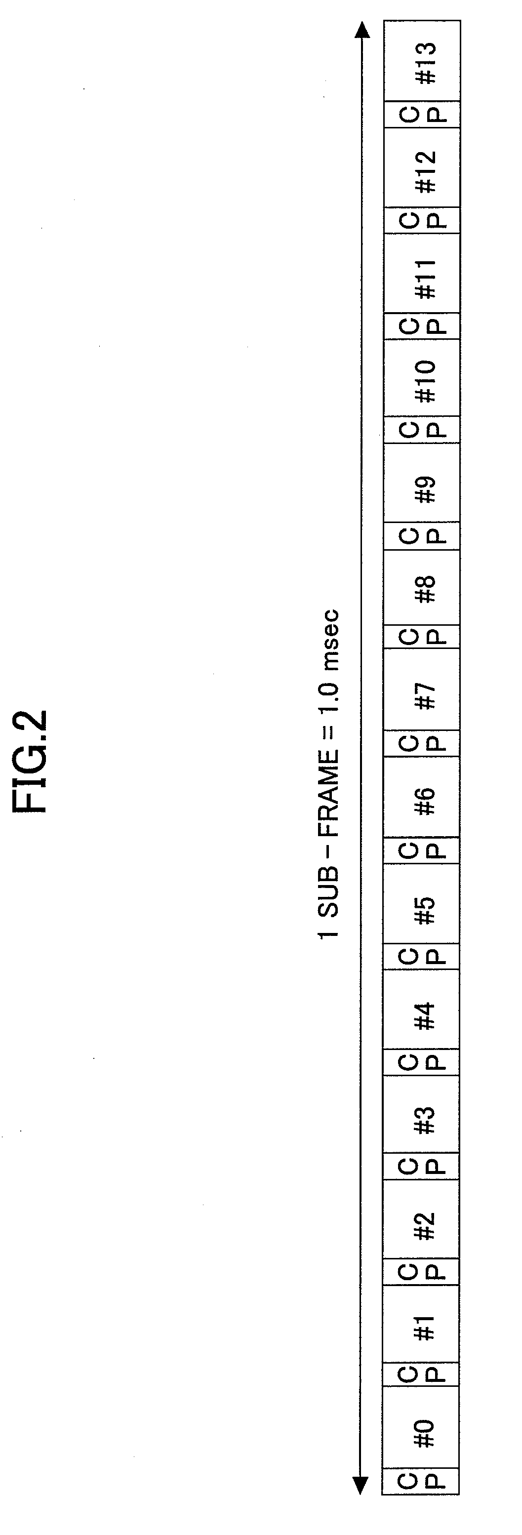
On the other hand, the number of sequences per one CAZAC code is limited to N−1 in the case of the sequence length of N. For this reason, when SC-FDMA symbols for RSs and SC-FDMA symbols for data signals are multiplexed according to TDM (shown in FIG. 2) as proposed in the E-UTRA uplink, there is a problem in that the sequence length of the RS cannot be long, and thus the number of sequences cannot be large.

Method used


Image

  • Mobile communication system
  • Mobile communication system
  • Mobile communication system

Examples


Embodiment Construction

Description of Notations

[0069]C1-C4, X-Z cell[0070]UE, UE1-UE4 user terminal[0071]CS control station[0072]101 frequency band determining unit[0073]102 frequency band information storing unit[0074]103 control signal generating unit[0075]111 frequency band priority determining unit[0076]112 frequency band priority information storing unit[0077]113 control signal generating unit[0078]121 scheduler[0079]122 control signal generating unit[0080]131 frequency hopping pattern determining unit[0081]132 frequency hopping pattern storing unit[0082]133 code changing pattern determining unit[0083]134 code changing pattern storing unit[0084]135 control signal generating unit[0085]141 timing determining unit[0086]BS, BS1-BS3 base station[0087]201 radio resource allocating unit[0088]202 receiving unit[0089]203 transmitting unit[0090]204 control information receiving unit[0091]205 channel condition measuring unit[0092]206 scheduler[0093]207 control signal generating unit[0094]211 radio resource allo...


PUM


Abstract

A mobile communication system in which a finite number of reference signal sequences used for uplink channel estimation or the like are reused among multiple cells includes a determining unit configured to determine a frequency band used by user terminals to which a reference signal sequence with a predetermined sequence length is assigned in each of the cells within an interference area, wherein the frequency band is determined to be different from frequency bands used in the other cells. Alternatively, the mobile communication system includes a changing unit configured to autonomously change to another of the reference signal sequences which does not cause interference, upon detecting interference from another of the cells to which the same reference signal sequence is assigned; a determining unit configured to randomly determine a frequency band or a reference signal sequence used by user terminals to which one of the reference signal sequences with a predetermined sequence length is assigned in each of the cells within an interference area; or a shifting unit configured to shift transmission timings of radio subframes in each of the cells within an interference area.

Description

BACKGROUND OF THE INVENTION[0001]1. Field of the Invention[0002]The present invention relates to a mobile communication system for avoiding collision among RSs (Reference Signals).[0003]2. Description of the Related Art[0004]In view of limitations of transmission power in a user terminal, an SC-FDMA (Single Carrier Frequency Division Multiple Access) scheme is proposed for an uplink radio access scheme in E-UTRA (Evolved UMTS (Universal Mobile Telecommunications System) Terrestrial Radio Access) standardized by 3GPP (3rd Generation Partnership Project), in order to reduce PAPR (Peak to Average Power Ratio) and to improve the efficiency of the transmitting amplifier (see “3GPP TR 25.813” V1.0.1 (2006-06), 3GPP Organizational Partners (ARIB, ATIS, CCSA, ETSI, TTA, TTC), for example). FIG. 1 shows an example of uplink frequency allocation in an SC-FDMA radio access scheme. In FIG. 1, signals for four user terminals UE1-UE4 are allocated on the frequency axis. It should be noted that a ...

Claims


Application Information

Patent Timeline
IPC IPC(8): H04W72/00H04J1/00H04W16/02H04W16/10H04W16/12H04W16/14H04W24/00H04W28/04H04W36/06H04W72/02H04W72/04
CPCH04J13/0059H04L5/0037H04W16/02H04L5/0091H04L5/0051H04J1/02H04W74/08
Inventor OFUJI, YOSHIAKIHIGUCHI, KENICHISAWAHASHI, MAMORU
Owner NTT DOCOMO INC
Learn More