

Relay device and relay method
- Summary
- Abstract
- Description
- Claims
- Application Information
AI Technical Summary
Benefits of technology
Problems solved by technology
Method used
Image

Examples
embodiment 1
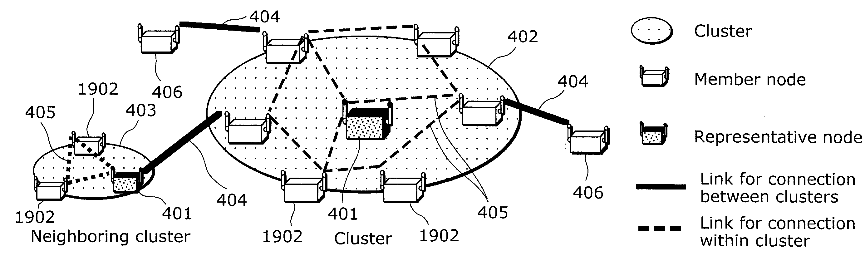
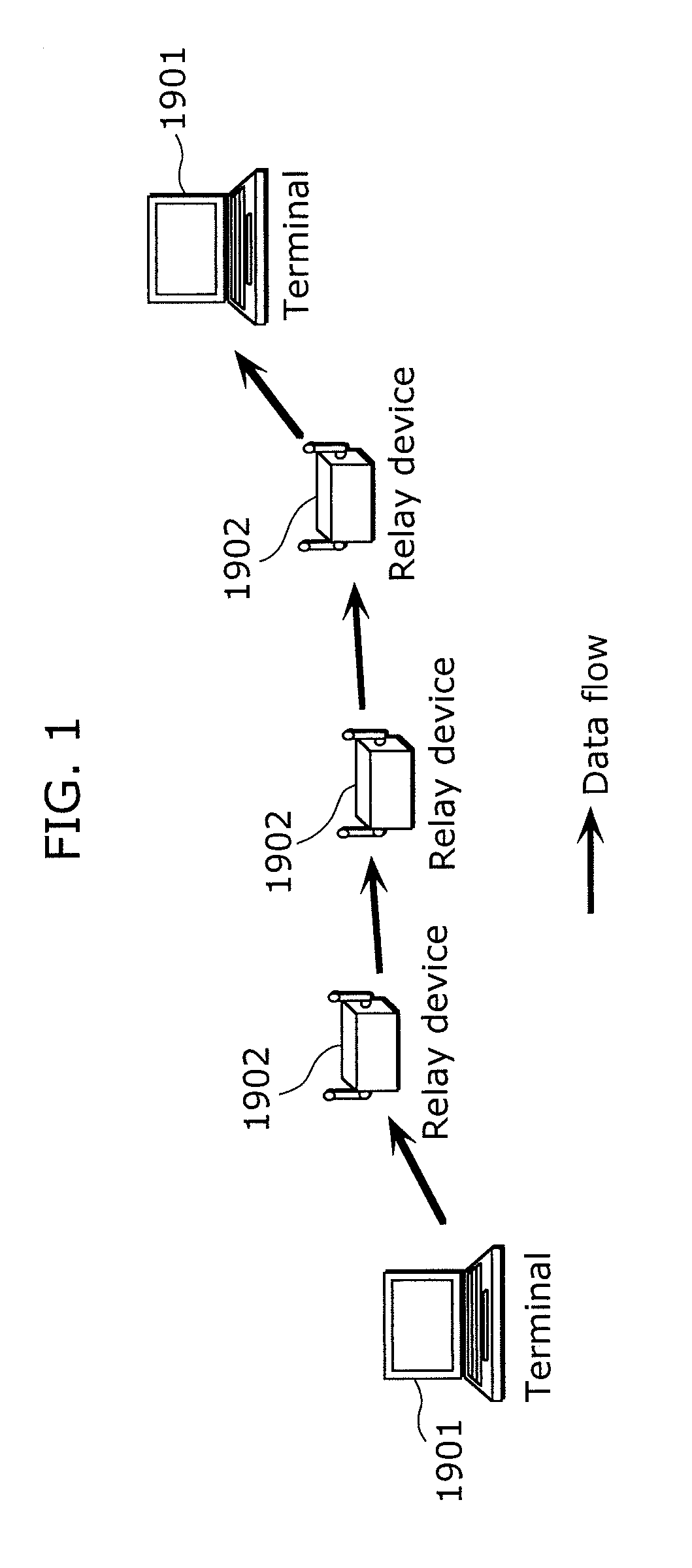
[0055]In the present invention, as shown in FIG. 3, clusters are formed each of which uses a common frequency channel based a range where a wireless packet communication is possible, in a wireless mesh network where relay devices are densely arranged. With this, multiple relay devices are considered as a single relay device, and wireless packets transmitted between terminals are relayed through multi-stages (multi-hop) via relay devices belonging to different clusters.
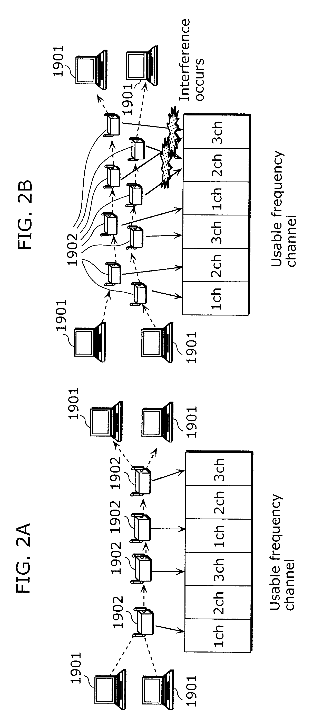
[0056]Further, interference of wireless packets is suppressed by assigning different frequency channels to neighboring clusters. This prevents wireless packets from being repeatedly relayed using a same frequency channel in a wireless mesh network where relay devices are densely arranged, thereby suppressing degradation in communication quality in the wireless mesh network.
[0057]Hereinafter, embodiments of the present invention will be described with reference to the drawings.
[0058]FIG. 4 is a diagram showing an exampl...
embodiment 2
[0158]Next, Embodiment 2 of the present invention is described. In Embodiment 2, by controlling the communication distance of wireless packets in addition to changing the frequency channel, interference of wireless packets caused between cluster members in the same cluster can be suppressed.
[0159]FIG. 19 is a block diagram showing a configuration of a relay device according to Embodiment 2. The relay device according to the present embodiment has a member counting unit 1601 and a wireless output adjusting unit 1602 in addition to the configuration of the relay device according to Embodiment 1 shown in FIG. 6. Note that the same elements as those included in the relay device in Embodiment 1 shown in FIG. 6 are assigned with the same referential number as in FIG. 6, and the descriptions thereof are not repeated.
[0160]The member counting unit 1601 refers to the neighboring cluster information 1101 obtained by the cluster information exchanging unit 603 to identify the number of the mem...
embodiment 3
[0170]Next, Embodiment 3 of the present invention is described.
[0171]Since communication is made wirelessly between the relay devices in the wireless mesh network, communication quality between the relay devices significantly varies depending on the change of time or place, compared to the wired network. One reason for this is that condition of radio wave shields or the position of reflective objects is changed due to, for example, the opening and closing of windows or doors. Further, another reason is that electromagnetic waves coming from surrounding lighting or home appliances such as a microwave causes interference.
[0172]Therefore, in the condition where the communication quality varies, the range in which the respective relay devices can communicate directly to other relay devices also varies. As a result, the size of the cluster changes due to the change of the members of the cluster managed per respective representative nodes. Further, clusters are generated or deleted by the...
PUM
 Abstract
Description
Claims
Application Information