
Intelligent Stepping For Humanoid Fall Direction Change

a robot and intelligent technology, applied in the direction of electric digital data processing, instruments, computing, etc., can solve the problems of robot slipping, tripping, or toppling, particularly worrisome falls, etc., and achieve the effect of maximizing the avoidance angl

Active Publication Date: 2010-06-24
HONDA MOTOR CO LTD
View PDF20 Cites 43 Cited by
  • Summary
  • Abstract
  • Description
  • Claims
  • Application Information

AI Technical Summary

Benefits of technology

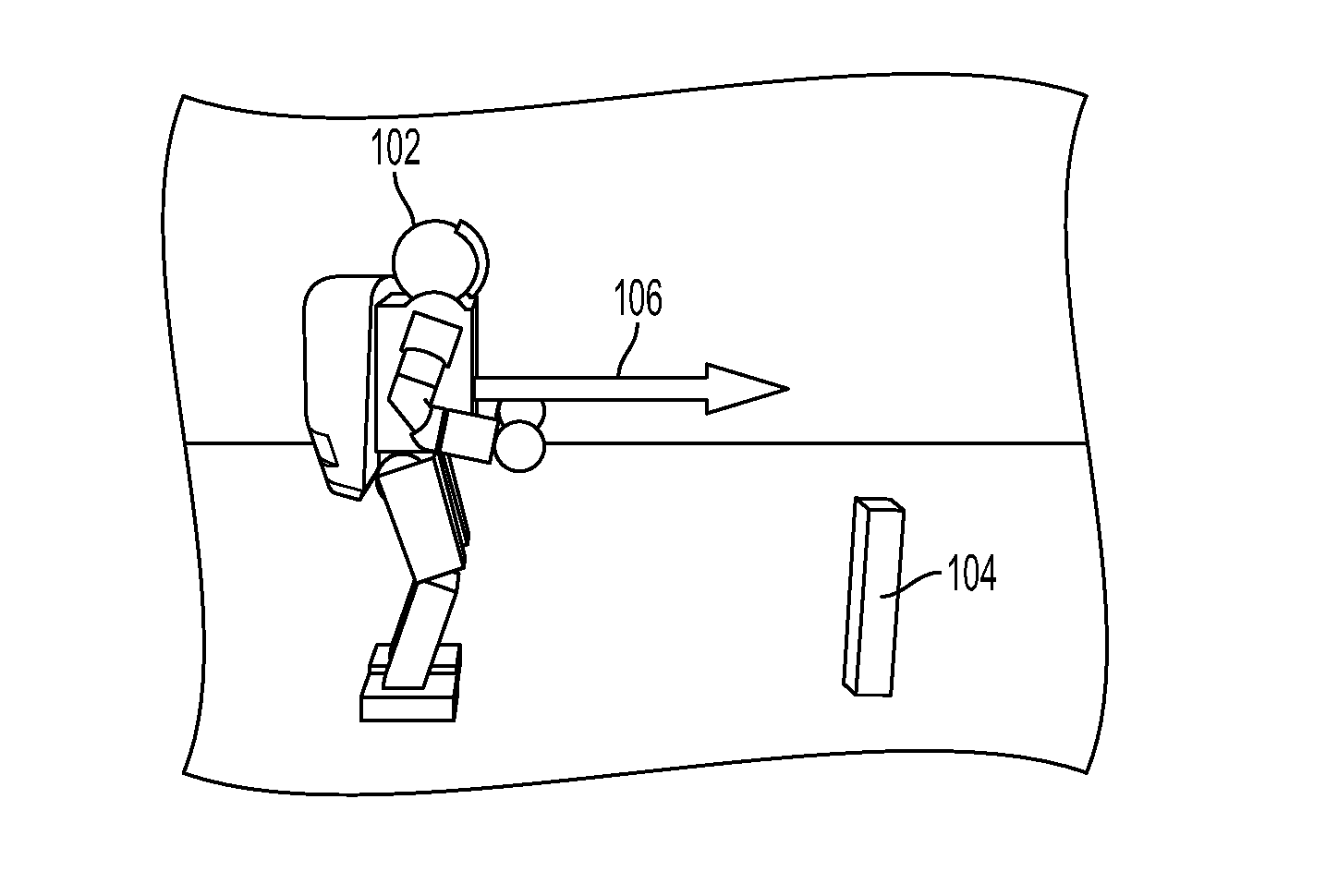
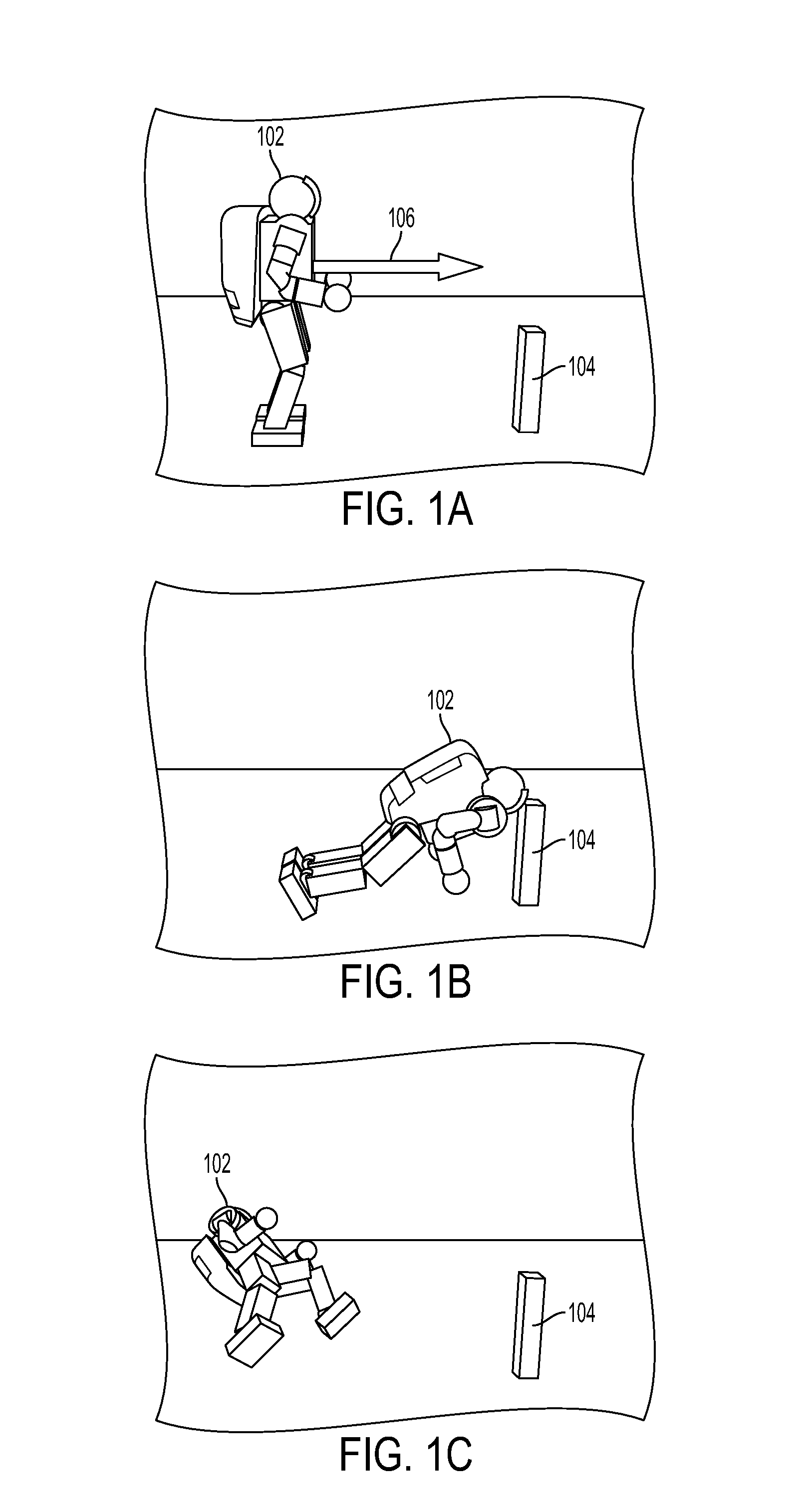
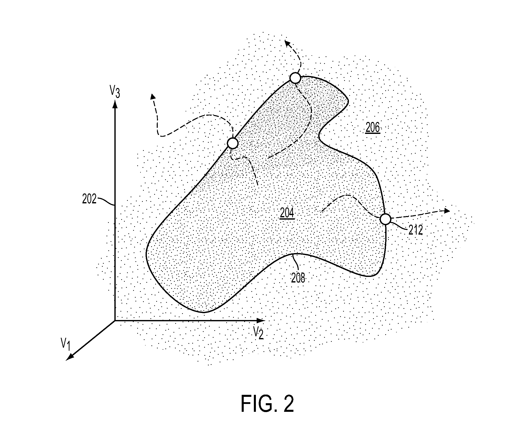
[0008]Embodiments of the invention provide techniques for controlling a robot having at least two legs that is falling down from an upright posture. An allowable stepping zone where the robot is able to step while falling is determined. The allowable stepping zone may be determined based on leg Jacobians of the robot and maximum joint velocities of the robot. A stepping location within the allowable stepping zone for avoiding an object is determi

Problems solved by technology

Out of a number of possible situations where safety becomes an issue, one that involves a fall is particularly worrisome.
A humanoid robot falling from an upright (e.g., standing or walking) posture can cause damage to delicate and expensive objects in the surroundings or injury to a nearby human being.
A humanoid robot fall may be caused due to unexpected or excessive external forces, unusual or unknown slipperiness, or the slope or profile of the ground.
The fall may involve the robot slipping, tripping, or toppling.
When the disturbances that threaten balance are larger than what the robot's balance controller can handle, the robot falls.
Regardless of the substantial progress in humanoid robot balance control strategies, the possibility of a fall, however remote, remains real, even unavoidable.

Method used


Image

  • Intelligent Stepping For Humanoid Fall Direction Change
  • Intelligent Stepping For Humanoid Fall Direction Change
  • Intelligent Stepping For Humanoid Fall Direction Change

Examples


Embodiment Construction

[0025]A preferred embodiment of the present invention is now described with reference to the figures where like reference numbers indicate identical or functionally similar elements. Also in the figures, the left most digits of each reference number corresponds to the figure in which the reference number is first used.

[0026]Reference in the specification to “one embodiment” or to “an embodiment” means that a particular feature, structure, or characteristic described in connection with the embodiments is included in at least one embodiment of the invention. The appearances of the phrase “in one embodiment” in various places in the specification are not necessarily all referring to the same embodiment.

[0027]Some portions of the detailed description that follows are presented in terms of algorithms and symbolic representations of operations on data bits within a computer memory. These algorithmic descriptions and representations are the means used by those skilled in the data processin...


PUM


Abstract

A system and method is disclosed for controlling a robot having at least two legs that is falling down from an upright posture. An allowable stepping zone where the robot is able to step while falling is determined. The allowable stepping zone may be determined based on leg Jacobians of the robot and maximum joint velocities of the robot. A stepping location within the allowable stepping zone for avoiding an object is determined. The determined stepping location maximizes an avoidance angle comprising an angle formed by the object to be avoided, a center of pressure of the robot upon stepping to the stepping location, and a reference point of the robot upon stepping to the stepping location. The reference point, which may be a capture point of the robot, indicates the direction of fall of the robot. The robot is controlled to take a step toward the stepping location.

Description

CROSS-REFERENCE TO RELATED APPLICATION[0001]This application claims the benefit of U.S. Provisional Application No. 61 / 139,442, filed Dec. 19, 2008, which is incorporated by reference in its entirety.[0002]This application is related to co-pending U.S. application No. ______, filed concurrently herewith, entitled “Inertia Shaping For Humanoid Fall Direction Change,” by Ambarish Goswami et al., which is incorporated herein in its entirety by reference. This application is also related to co-pending U.S. application Ser. No. 11 / 946,702, filed Nov. 28, 2007, entitled “Determination of Foot Placement for Humanoid Push Recovery,” which is incorporated herein in its entirety by reference.BACKGROUND OF THE INVENTION[0003]1. Field of the Invention[0004]The present invention relates to controlling the motion of a robot.[0005]2. Description of Background Art[0006]Safety is a primary concern that should be addressed before humanoid robots can freely exist in human surroundings. Out of a number...

Claims


Application Information

Patent Timeline
IPC IPC(8): G06F19/00
CPCB62D57/032
Inventor GOSWAMI, AMBARISHYUN, SEUNG-KOOKSAKAGAMI, YOSHIAKI
Owner HONDA MOTOR CO LTD
Learn More