Adjustable base for an optic

a technology of optics and base, applied in the field of optics gun sight mounts, can solve problems such as unsuitable solutions, and achieve the effect of rapid adjustment of target rang

Inactive Publication Date: 2010-07-01
LWRC INTERNATIONAL
View PDF5 Cites 80 Cited by
  • Summary
  • Abstract
  • Description
  • Claims
  • Application Information

AI Technical Summary

Benefits of technology

[0012]The present invention is designed to address the problem of adjusting the current target range of a gun sight by providing an apparatus which allows for the rapid adjustment of the target range through the external adjustment of the gun sights elevation, thereby affecting the trajectory of a discharged projectile. The herein described device accomplishes this by providing a vertically adjustable bridge which has a mount platform for the gun, sight and may be secured to a base that attaches to the host firearm. From the standpoint of ballistics, the mount is designed to provide the correction in elevation to the scope according with the trajectory of the projectile. The mount has a graduated knob which is integral to the adjustment cam, with set distances, to be selected with one hand from the aiming position. In other words, the distance or target range can be selected while the shooter is looking though the gun sight.

Problems solved by technology

These prior art solutions, while providing a means to “sight in” the weapon in a range environment, are not suitable solutions for those needing to adjust the elevation and trajectory of a discharged projectile using the gun sight in a combat or action shooting competition.

Method used


Image

  • Adjustable base for an optic
  • Adjustable base for an optic
  • Adjustable base for an optic

Examples


Embodiment Construction

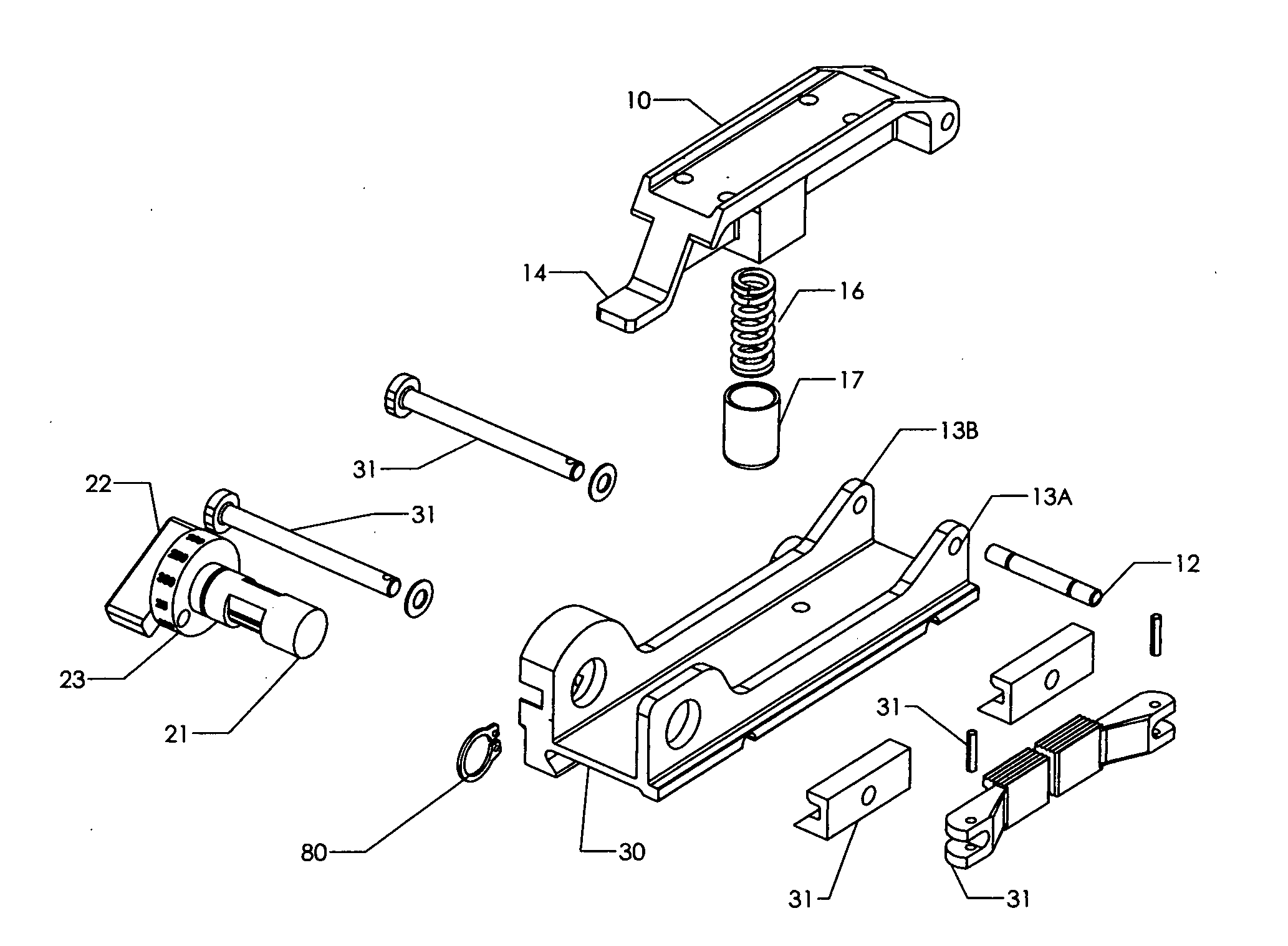
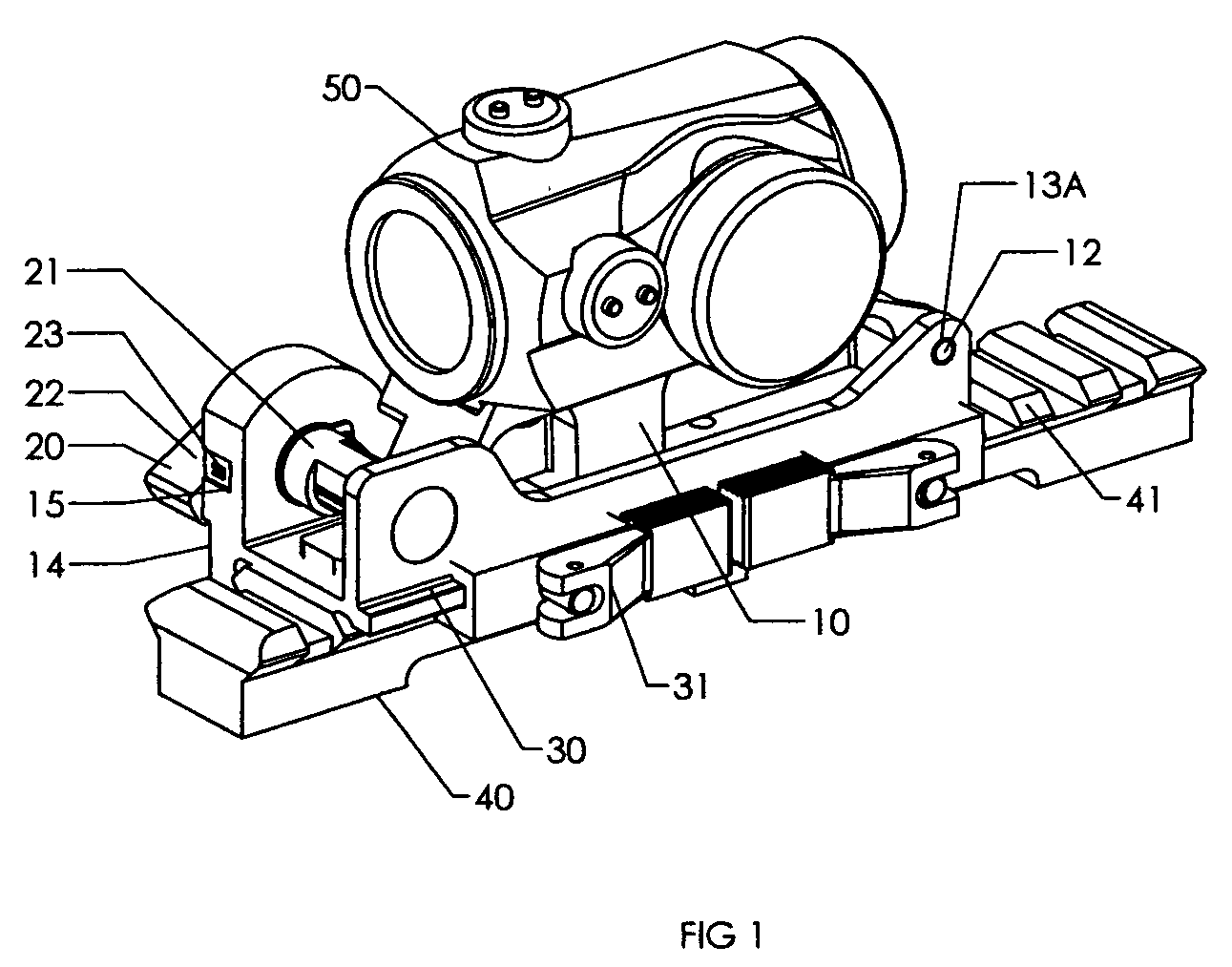
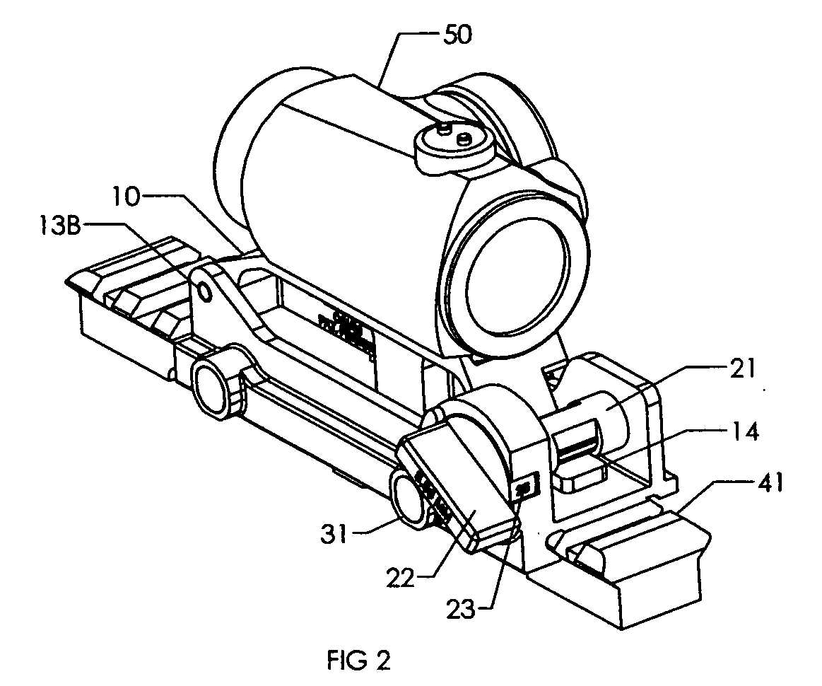
[0027]Now referring to the drawings, the adjustable base for an optic 1 assembly of the present invention is shown and generally illustrated in the figures. While the assembly may include several components and auxiliary attachments to tailor the assembly for the particular application, in the simplest form, the present invention provides for a device utilizing a spring loaded rail which is in operational connection with a cam that allows the user to adjust the elevation of an auxiliary sighting device, specifically an electronic optic with a firearm. In the preferred embodiment, the required components include at least an adjustable gun sight bridge 10 with an optic mounting platform 11, and an adjustment cam 20, and a base 30 which interfaces with the host firearm. Additionally, other components that may be utilized in the assembly as required by the particular application include a throw lever retention system 31 or simply screws.

[0028]As was stated above, the adjustable base for...


PUM


Abstract

A gun sight base which is designed to allow the user to quickly adjust the elevation of the attached gun sight as a means to affect the trajectory of a projectile discharged from the host firearm. Provided is a removable, pre-calibrated adjustment cam which is in operational contact with the attached gun sight. A distance indicator is visible to the user to allow for rapid elevation adjustments without the need for tools.

Description

BACKGROUND OF THE INVENTION[0001]1. Field of Invention[0002]The herein disclosed invention relates, in general, to optical gun sight's for use with a firearm and specifically for optical gun sight mounts.[0003]2. Prior Art[0004]Telescopic and electronic gun sights for use on rifles and other firearms are well known in the prior art. Adapting these gun sights to various weapons, in general, involves mounting the gun sight containing an image of a red dot or other physical reticule which is used to designate and aim upon a target and a means for mounting the gun sight onto a weapon. In general, the preferred method of securing a gun sight to a mount was through the use of at least one ring which encircles the gun sight and a mount which is designed to be secured to a secondary surface such as a 1913 mil. std. rail that is parallel to the bore of the host firearm. These conventional systems rely on the ring or rings which encircle the gun sight to be securely mounted to a base which co...

Claims


Application Information

Patent Timeline
Patent Type & Authority Applications(United States)
IPC IPC(8): F41G1/387
CPCF41G1/18F41G1/28F41G11/003
Inventor SAMSON, WILLIAMCORREA, RAFAEL
Owner LWRC INTERNATIONAL
Why Eureka
Try Eureka