Stripper plate mounting apparatus

Active Publication Date: 2010-07-01
AMADA CO LTD
View PDF8 Cites 2 Cited by
  • Summary
  • Abstract
  • Description
  • Claims
  • Application Information

AI Technical Summary

Benefits of technology

[0016]The first to fourth aspects of the present invention makes it possible to fix the adaptor holding the stripper plate to the punch guide by use of the lock mechanisms, and to remove the adaptor from the punch guide by releasing the adaptor from the fixation by use of the lock mechanisms. For this reason, the adaptor is not pushed up by the punch guide. Regardless of the weight of the stripper plate, the adaptor h

Problems solved by technology

As learned from the foregoing descriptions, the conventional configuration has a problem that the multiple lock buttons 31 have to be simultaneously pressed against the respective springs 33.
In addition, because the holder 23 is pushed upward by the biasing forces from the springs 25

Method used


Image

  • Stripper plate mounting apparatus
  • Stripper plate mounting apparatus
  • Stripper plate mounting apparatus

Examples


Example

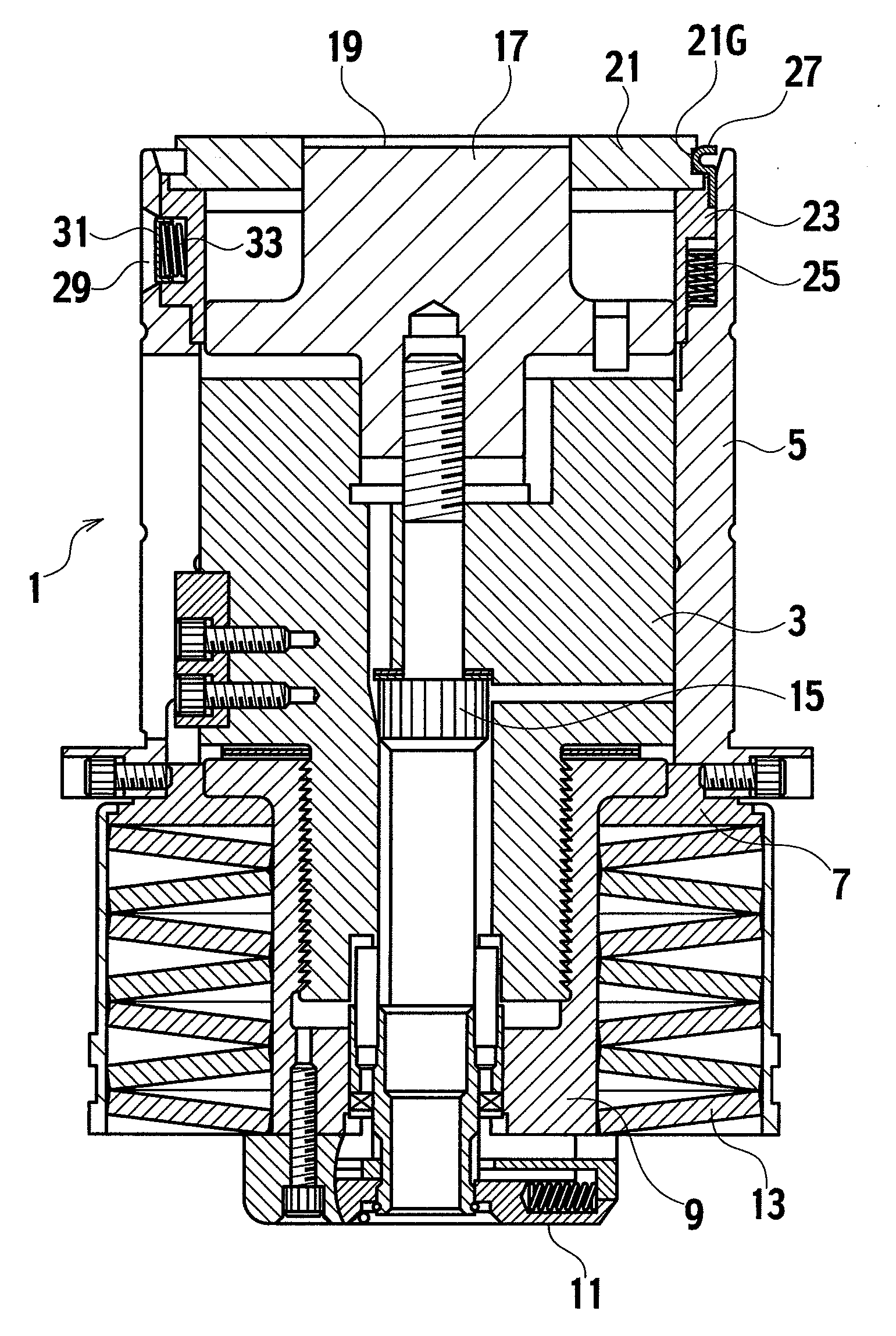
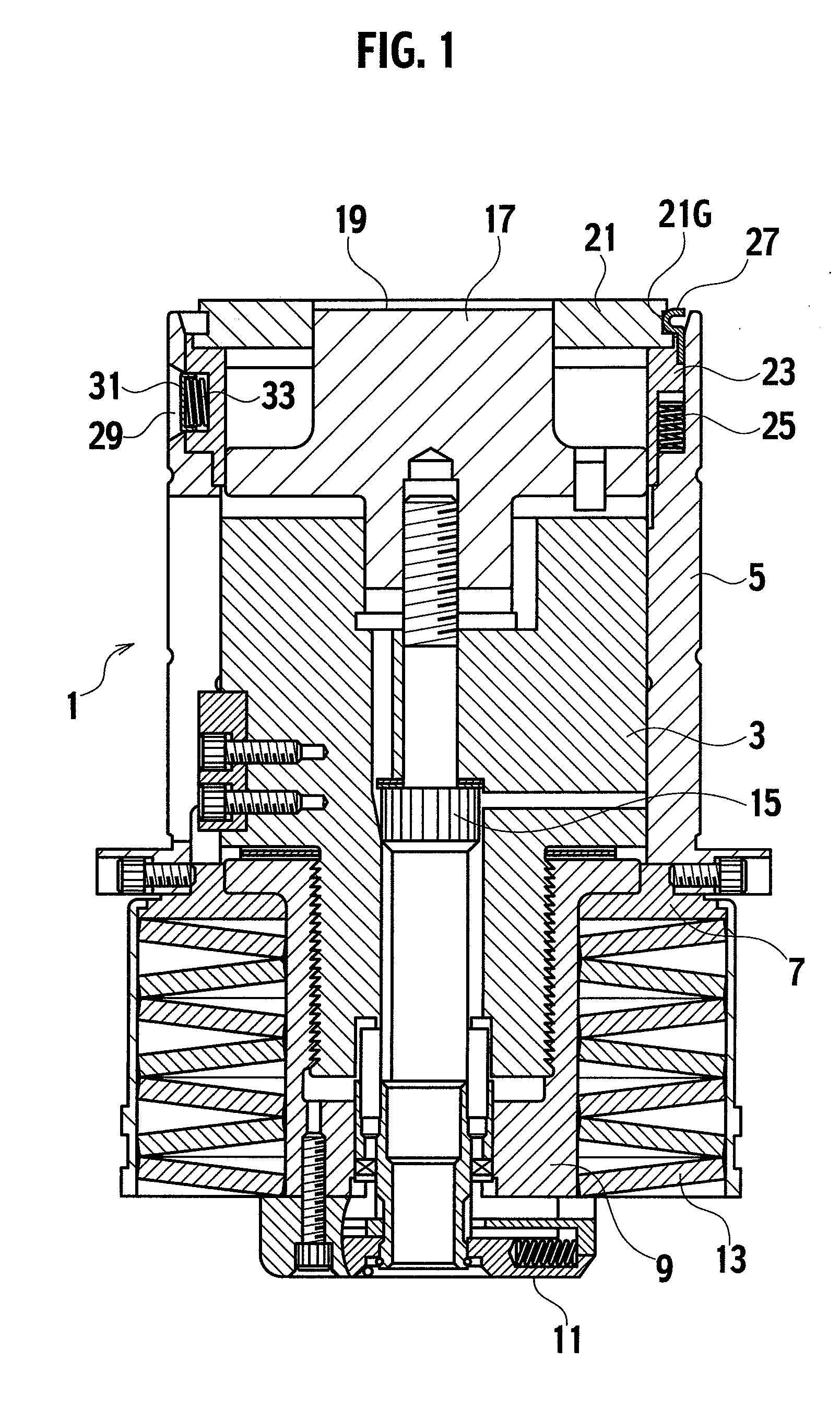
[0022]Referring to the drawings, descriptions will be provided hereinbelow for an embodiment of the present invention. Components which play the same functions as components in the above-described conventional configuration are denoted by the same reference numerals, and duplicated descriptions will be omitted. In addition, the overall configuration of the punch die is almost the same as the general configuration of the conventional type of punch die. For this reason, illustrations and descriptions for the overall configuration of the punch die will be omitted. Instead, detailed descriptions will be provided for a configuration for mounting the stripper plate in a detachable and replaceable manner on the punch guide.

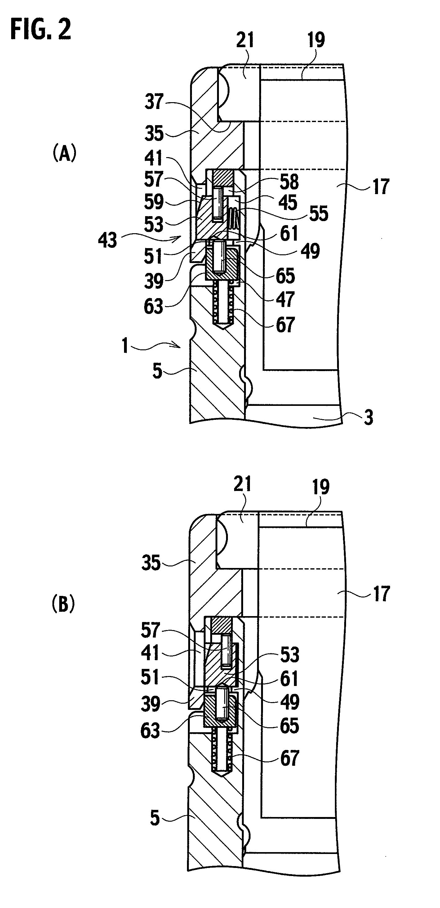
[0023]Referring to FIGS. 2(A) and 2(B), the overall configuration of a punch die 1 is almost the same as the configuration of the conventional type of general punch die. Like the conventional type of punch guide, a punch body 3 is fitted into a cylindrical punch guide 5 ...


PUM


Abstract

A stripper plate mounting apparatus is for mounting a stripper plate (21) in a detachable and replaceable manner on a front end portion of a punch guide (5) into which a punch (17) is fitted movably upward and downward. The apparatus includes: an adaptor (35), for holding the stripper plate (21), detachably provided in a front end portion of the punch guide (5); and lock mechanisms (43), capable of fixing the adaptor (35) to the punch guide (5), provided in multiple locations on the outer periphery of the front end portion thereof. The lock mechanisms (43) each include: a lock piece (53) which is always biased outward in a radial direction by biasing means, and which is engageable with, and detachable from, the lock part (41); and a lock-holding piece (63) for locking and holding the lock piece (53) to an inward position when the lock piece (53) is pressed and moved inward in the radial direction.

Description

TECHNICAL FIELD[0001]The present invention relates to a stripper plate mounting apparatus for mounting a stripper plate in a detachable and replaceable manner on a punch die used for punch press. Specifically, the present invention relates to a stripper plate mounting apparatus capable of easily attaching and detaching a stripper plate to and from a punch die.BACKGROUND ART[0002]A punch die used for punch press is provided with a stripper plate for pressing down the die to a plate-shaped workpiece, while the workpiece is processed in a punching process with a punch, for the purpose of preventing a deformation of punching during the punching process. When the edge part of the punch is worn, the punch is removed from the punch die, and the edge part is ground again. In this case, it is necessary to remove the stripper plate from the punch die. With this background, proposals have been made on a configuration which allows the stripper plate to be mounted on and detached from the punch ...

Claims


Application Information

Patent Timeline
IPC IPC(8): B21D45/08
CPCB21D45/006B26D7/00B26D7/1818B26F1/40Y10T83/2159Y10T83/9476B21D28/00B21D28/14B21D45/08
Inventor NAKAI, HIROSHI
Owner AMADA CO LTD
Why Eureka
Try Eureka