Disk Brake Having a Pad-Retaining Clip and a Securing Device, and Brake Pad Set

Active Publication Date: 2018-09-06
KNORR-BREMSE SYST FUER NUTZFAHRZEUGE GMBH
View PDF9 Cites 2 Cited by
  • Summary
  • Abstract
  • Description
  • Claims
  • Application Information

AI Technical Summary

Benefits of technology

[0026]For certain installation situations, it may be advantageous that the at least one resilient arm of the bracket element is connected to in each case at least one hook-shaped end section via a forked portion.
[0027]In another embodiment, the at least one resilient arm of the bracket element is equipped with at least one actuation section. This yields the advantage that, during a dismounting process, a release of the engagement by pressing against the spring force of the resilient arm is made easier.
[0028]A further embodiment provides that the retainer has two retaining sections, of which in each case one is attached to one side of a face section at right angles with respect to the face section and has in each case one opening which is in each case in engagement with a hook-shaped end section of the bracket element in the installed state of the pad retaining clip, wherein the bracket element is formed in the manner of a strip and includes a face section which is arranged in front of and fastened to the end section of the pad retaining clip. In each case one resilient arm with a hook-shaped end section is attached by a rounded face section to each side of the face section, wherein the end sections with the resilient arms for engagement with the respective opening of the associated retaining section are moved resiliently away from one another during the mounting of the pad retaining clip, and moved toward one another counter to the spring force of the resilient arms during the release of the engag

Problems solved by technology

In the worst case, the pad retaining clip may under some circumstances slip during operation and impair a securing action of the brake pads.
The openings offer advantageous restraint of those sections of the bracket element which are in

Method used


Image

  • Disk Brake Having a Pad-Retaining Clip and a Securing Device, and Brake Pad Set
  • Disk Brake Having a Pad-Retaining Clip and a Securing Device, and Brake Pad Set
  • Disk Brake Having a Pad-Retaining Clip and a Securing Device, and Brake Pad Set

Examples


Example

[0136]In this second embodiment of the securing device 10, the retainer 12′ is integrated into the rear-side pad rear plate 5a.

[0137]The retainer 12′ integrated into the pad rear plate 5a comprises in this case two through openings 51, with web sections 5c and recesses 52.

[0138]The openings 51 are formed as through openings 51, for example with a rectangular cross section, running in the y3 direction in the upper region of the pad rear plate 5a. The y3 direction corresponds in this case to the y direction from FIG. 1 and runs in the direction of the brake disk axis of rotation 2. The web sections 5c form in each case an upper delimitation of each opening 51. The recesses 52 are formed on the pad side of the pad rear plate 5a around the openings 51 into the pad rear plate 5a, whereby a thickness of the web sections 5c in this region in the y3 direction is reduced to approximately half of a thickness of the pad rear plate 5a, and retaining surfaces 5d are formed. The retaining surfac...

Example

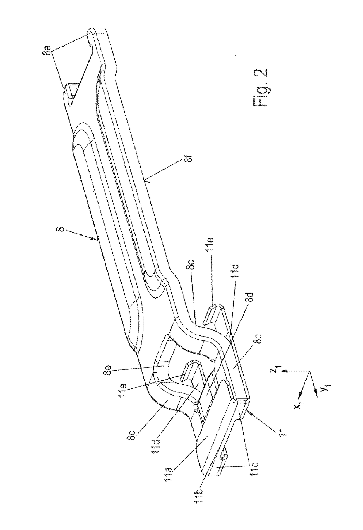
[0141]FIGS. 15 and 16 show schematic perspective views of variants of the first embodiment of the securing device 10.

[0142]FIG. 15 shows a retainer 12″ which is attached to the rear surface 5b of the rear-side pad rear plate 5a. The retainer 12″ comprises a plate section 12a, a face section 12b with a retaining section 12c, and a side section 12′h.

[0143]The retainer 12″ is formed for example for interacting with the end sections 11e of the variant of the bracket element 11 as per FIG. 12b.

[0144]The plate section 12a has, on its first longitudinal side which projects from the rear surface 5b in the positive y direction, a face section 12b which simultaneously forms a retaining section 12c. The side section 12′h is attached to the other longitudinal side of the plate section 12a and runs in its x-z plane parallel to the x-z plane of the face section 12b / retaining section 12c. The face section 12b / retaining section 12c has an extent in the negative z direction which corresponds appro...


PUM


Abstract

A disk brake for a vehicle, in particular for a utility vehicle, is provided. The disk brake includes a brake disk, a brake caliper with application and back sections, brake pads having pad back plates with a pad-retaining spring supported under preload by a pad-retaining clip on the brake caliper, and a securing device releasably securing the pad-retaining clip via the pad back plate of the back-side brake pad. The securing device has at least one clip element and at least one retainer. In an installed state, at least one section of the at least one clip element is in engagement with at least one section of the retainer. During installation/removal of the pad-retaining clip, the at least one clip element section can be moved against a spring force. A corresponding brake pad set is provided.

Description

CROSS REFERENCE TO RELATED APPLICATIONS[0001]This application is a continuation of PCT International Application No. PCT / EP2016 / 075888, filed Oct. 27, 2016, which claims priority under 35 U.S.C. § 119 from German Patent Application No. 10 2015 118 838.4, filed Nov. 3, 2015, the entire disclosures of which are herein expressly incorporated by reference.BACKGROUND AND SUMMARY OF THE INVENTION[0002]The present invention relates to a disk brake having a pad retaining clip and securing device. The invention also relates to a brake pad set for a disk brake of said type.[0003]Brake pads of disk brakes, in particular pneumatic disk brakes, in vehicles, for example utility vehicles, are held in so-called pad slots by a pad retaining clip. In order that the pad retaining clip cannot be displaced out of its position by lateral forces in the vehicle, additional components are required which not only prevent a displacement of the retaining clip, in particular during operation, but also permit mo...

Claims


Application Information

Patent Timeline
IPC IPC(8): F16D65/097
CPCF16D65/0978F16D2055/007F16D2250/0084F16D65/097
Inventor KRAUSE, OLIVERKLINGNER, MATTHIASSCHOEFBERGER, TOBIAS
Owner KNORR-BREMSE SYST FUER NUTZFAHRZEUGE GMBH
Why Eureka
Try Eureka