Lubricating apparatus and method for dosing cylinder lubrication oil

a technology of lubricating apparatus and cylinder, which is applied in the direction of engine lubrication, lift valve, rotary slide valve, etc., can solve the problems of difficult connection with conventional lubricating apparatus

Active Publication Date: 2010-07-01
HANS JENSEN LUBRICATORS
View PDF9 Cites 18 Cited by
  • Summary
  • Abstract
  • Description
  • Claims
  • Application Information

AI Technical Summary

Benefits of technology

[0023]This principle is thus based on the fact that two or more types of hydraulic pistons are used, where a first group of hydraulic pistons can be extended up through the distributor plate, thereby preventing the distributor plate from moving to an extreme position. When a second piston group is activated, the distributor plate may be moved to the extreme position and be stopped by the base block.
[0024]It is noted that each group of hydraulic pistons is only required to comprise one hydraulic piston. Hereby is achieved a simple and compact design. This design can be particularly simple and compact if the hydraulic pistons are provided telescoping with several pistons disposed within each other.
[0025]The telescoping hydraulic pistons may preferably be cylindric and disposed coaxially, as hereby there is achieved a particularly simple design enabling quantity adjustment of the cylinder lubricating oil by arbitrary extension of the telescoping piston unit for desired discharge of cylinder lubricating oil. This may be controlled by an algorithm in an electronic control unit / computer.

Problems solved by technology

This has been used for point lubrication, but it is difficult to establish in connection with conventional lubricating apparatuses.

Method used


Image

  • Lubricating apparatus and method for dosing cylinder lubrication oil
  • Lubricating apparatus and method for dosing cylinder lubrication oil
  • Lubricating apparatus and method for dosing cylinder lubrication oil

Examples


Embodiment Construction

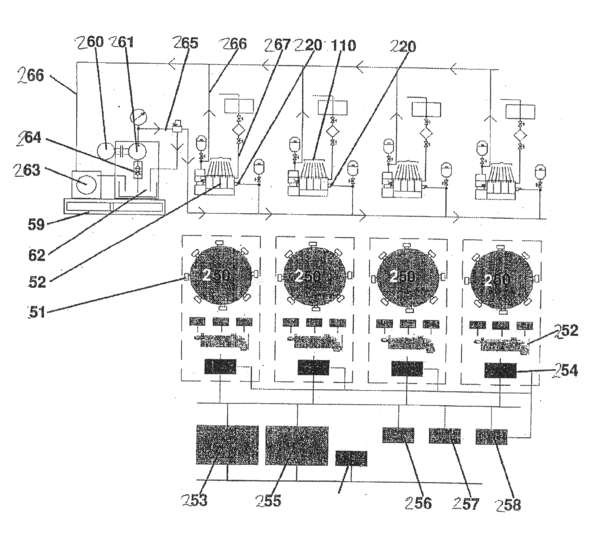
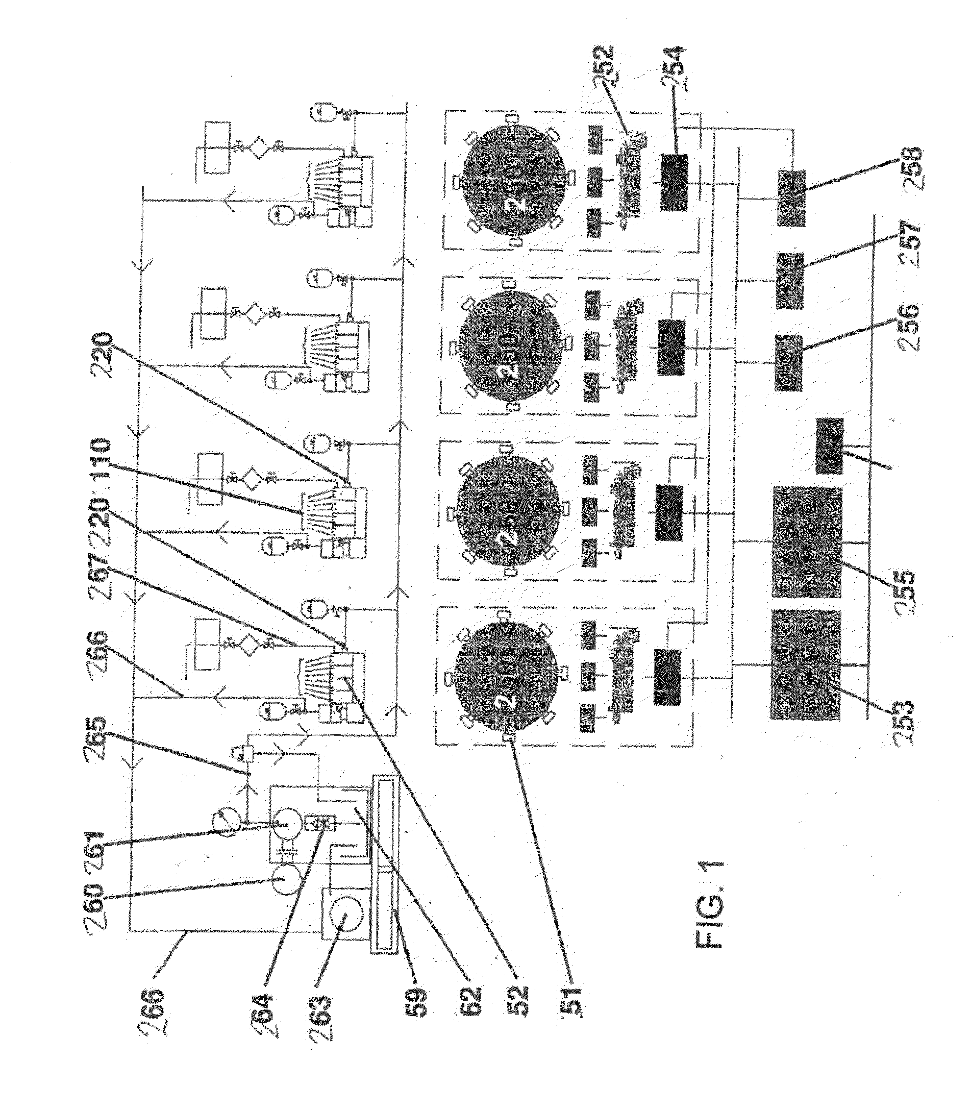
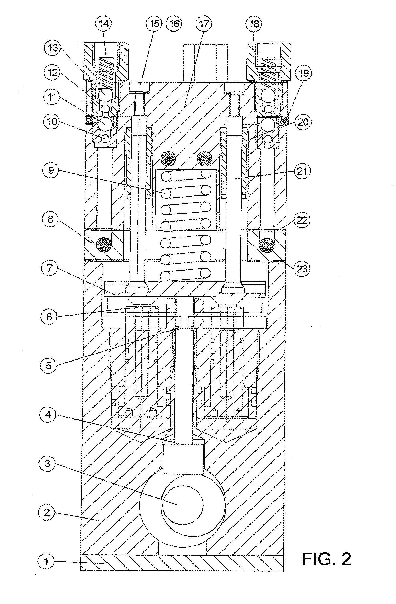
[0016]According to the present invention, this is achieved by a lubricating apparatus of the type specified in the introduction, which is peculiar in that the hydraulic pistons are provided in groups, that each group is adapted for independent displacement of the distributor plate for actuating the dosing pistons, and that each group of hydraulic pistons have each their individual stroke.

[0017]The method according to the invention is peculiar in that the hydraulic pistons are provided in groups, that each group independently displace the distributor plate for actuating the dosing pistons, and that each group of hydraulic pistons have each their individual stroke.

[0018]According to an advantageous embodiment, the method is peculiar in that only one hydraulic piston is used for each group.

[0019]In that way there may be achieved an individual quantity adjustment of lubricating oil, depending on the group of hydraulic pistons that is activated.

[0020]A distributor plate is used for drivi...


PUM


Abstract

There is described a hydraulic lubricating apparatus (252) for dosing cylinder lubricating oil, including a housing which via one or more valves (220) is connected to a source for supplying hydraulic oil (262) and cylinder lubricating oil (not shown), a number of hydraulic cylinders each having a hydraulic piston (6) and which may be pressurised by hydraulic oil. Furthermore, there are a number of injection units (251) corresponding to a multiple of the cylinder (250) number in the engine, and which are connected with each their dosing cylinder by a dosing piston (21). Also, there is provided a distributor plate (7) which at one side is in contact with the dosing pistons (21) and which at its other side is in contact with the hydraulic pistons (6) for displacing the distributor plate for actuating the dosing pistons. The hydraulic pistons (6) are provided in groups, where each group is adapted for independent displacement of the distributor plate (7) for actuating the dosing pistons, and where each group of hydraulic pistons have each their individual stroke. In that way there may be achieved an individual quantity adjustment of lubricating oil, depending on the group of hydraulic pistons that is activated.

Description

FIELD OF THE INVENTION[0001]The present invention concerns a hydraulic lubricating apparatus for dosing cylinder lubricating oil, e.g. in marine engines, the lubricating apparatus including[0002]a housing which via one or more valves is connected with a source for supplying hydraulic oil and cylinder lubricating oil;[0003]a number of hydraulic cylinders that each have a hydraulic piston and which may be pressurised by hydraulic oil;[0004]a number of injection units corresponding to a multiple of the cylinder number in the engine, and which are connected with each their dosing cylinder with a dosing piston;[0005]a distributor plate which at one side of it is in contact with the dosing pistons and which at its other side is in contact with the hydraulic pistons for displacing the distributor plate for actuating the dosing pistons.[0006]Moreover, the invention concerns a method for a dosing cylinder lubricating oil, e.g. in marine engines, the method including:[0007]a supply of hydraul...

Claims


Application Information

Patent Timeline
Patent Type & Authority Applications(United States)
IPC IPC(8): F01M1/16
CPCF01M1/08F01M1/14F01M1/16F01M2001/083F01M1/02
Inventor AAMAND, JANBAK, PEER
Owner HANS JENSEN LUBRICATORS
Why Eureka
Try Eureka