Container conveyer device

a conveyer device and container technology, applied in the direction of conveyor parts, transportation and packaging, coatings, etc., can solve the problems of difficult shortening the time for forming films, and achieve the effects of shortening the time for feeding and discharging containers, improving production efficiency, and increasing the speed of conveyan

Inactive Publication Date: 2010-07-01
TOYO SEIKAN KAISHA LTD
View PDF15 Cites 1 Cited by
  • Summary
  • Abstract
  • Description
  • Claims
  • Application Information

AI Technical Summary

Benefits of technology

[0017]In the container conveyer device of the present invention, the conveyer passage has the inner conveyer passage that rotates about the rotary shaft, the outer conveyer passage arranged on the outer circumferential side thereof, the conveyer feed means for feeding the containers to either the inner conveyer passage or the outer conveyer passage, and container discharge means for discharging the containers to the other conveyer passage, so that the containers are returned back to the other conveyer passage after the containers are taken out from the one conveyer passage at the container hand-over position. Further, the inner conveyer passage and the outer conveyer passage are independently controlled so that the containers can be fed and discharged at separate timings. It is, therefore, made possible to convey the containers at high speeds. More closely, unlike the conventional device (FIG. 12), the container conveyer device does not require a plurality of branch passages or conveyer passage change-over points, does not require the time such as waiting for the change over of the container conveyer passages, and makes it possible to shorten the time for feeding and discharging the containers. Upon increasing the speed of conveyance, the containers can be conveyed to meet the treating capability of the device contributing to improving the production efficiency.
[0018]Despite there are a plurality of container-treating devices (vapor deposition devices) on the way of the conveyer passage, the system as a whole does not extend straight, and the area for installation can be effectively utilized. The conventional device was provided with the container feed conveyer passage and the container discharge conveyer passage or, substantially, with four conveyer passages inclusive of branch passages to convey the containers requiring an increased area for installation. The present invention, on the other hand, requires the container feed conveyer passage and the discharge conveyer passage only, though the conveyer passages have dissimilar shapes, making it possible to decrease the area for installation.

Problems solved by technology

Arrangement of the plurality of discharge portions on the way of the conveyer passage, however, causes the device to become bulky making it difficult to shorten the time for forming the films.

Method used


Image

  • Container conveyer device
  • Container conveyer device
  • Container conveyer device

Examples


Embodiment Construction

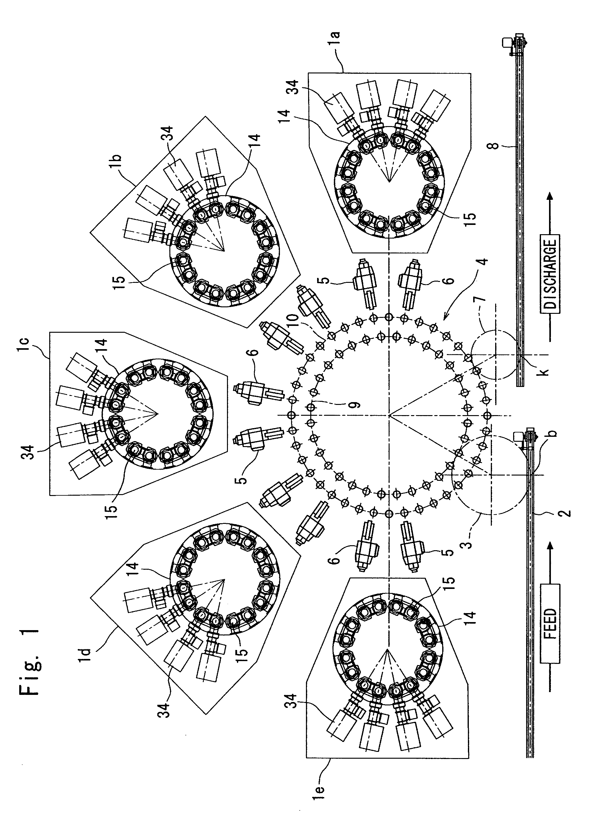
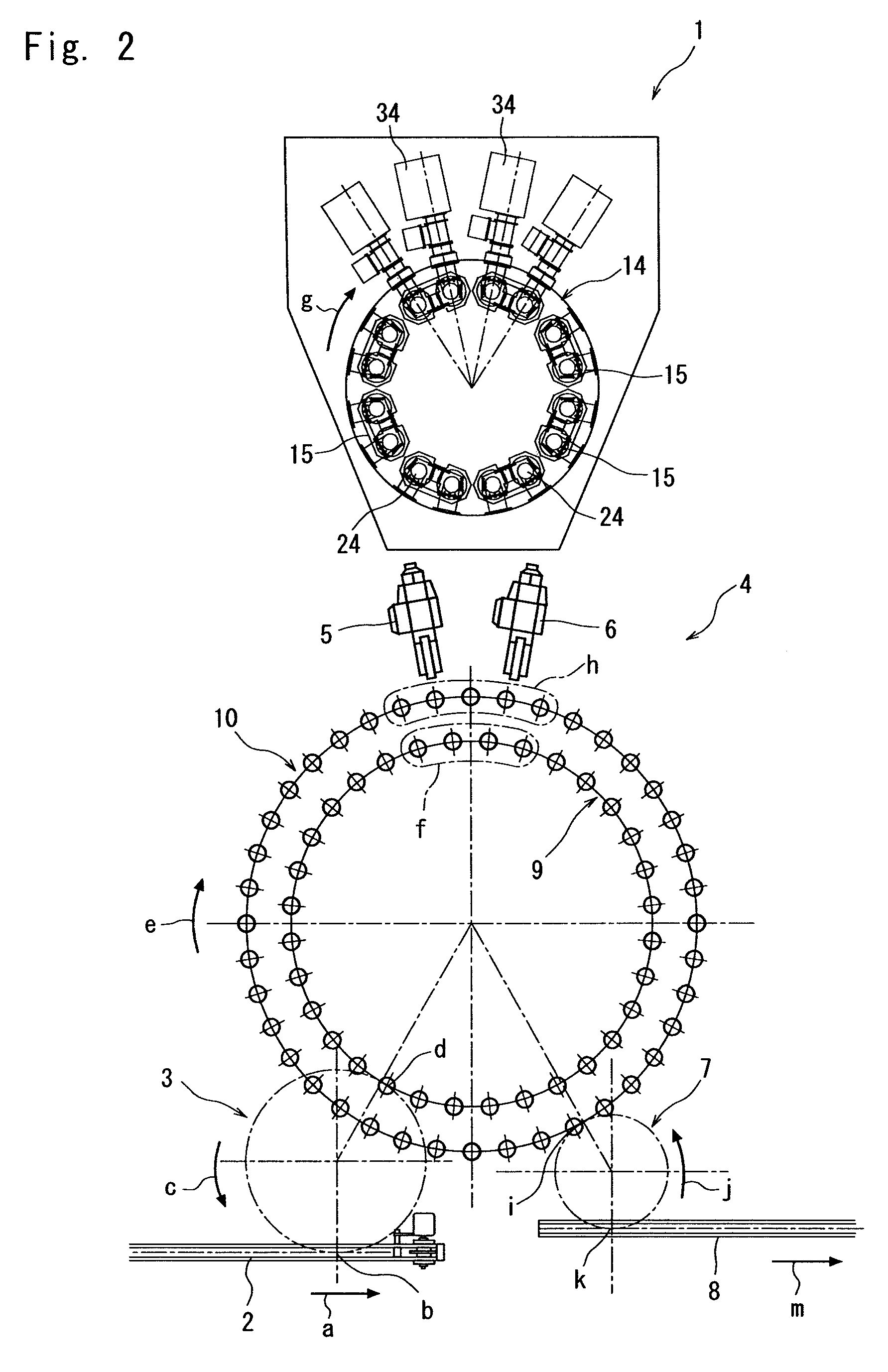
[0089]FIG. 1 is a plan view of a vapor deposition system for containers equipped with a container conveyer device according to the present invention, and FIG. 2 is an enlarged plan view of the vapor deposition system (only one vapor deposition device 1 is shown here due to the space of the drawing).

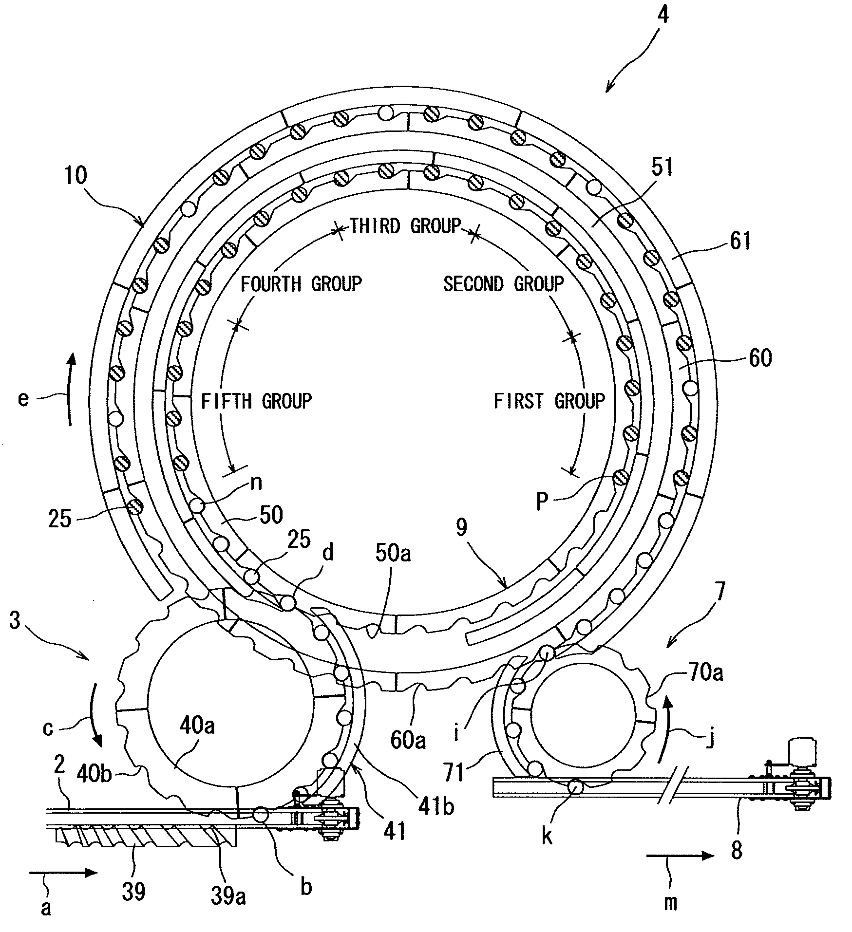
[0090]The vapor deposition system works to deposit the vapor of a functional starting material on the inner surfaces of the containers by utilizing microwaves while the containers move through the vapor deposition system from the upstream side thereof to the downstream side thereof. The containers 25 flow to a feed conveyer 2 positioned on the upstream of the vapor deposition system, container feed wheel 3, conveyer wheel 4, container hand-over devices (delivery robots) 5, 6, and to the vapor deposition device 1, and are returned back again to the container hand-over devices 5, 6 and to the conveyer wheel 4, and, further, flow from the conveyer wheel 4 to a container discharge wheel 7 and...


PUM

PropertyMeasurementUnit
heightaaaaaaaaaa
speedaaaaaaaaaa
areaaaaaaaaaaa

Abstract

[Problems] To decrease the area for installing a container conveyer passage that has container hand-over devices on the way of the conveyer passage.[Means for Solution] A container conveyer device including a conveyer passage that has a container feed position d where containers are received and a container discharge position i where the containers are handed over, and for conveying the containers from the container feed position d up to the container discharge position i, the container conveyer device, further, having container hand-over positions f, h where the containers that are once taken out from the conveyer passage are returned back again to the conveyer passage on the way of the container conveyer passage. A conveyer wheel 4 includes an inner conveyer passage 9 and an outer conveyer passage 10 that rotate about a rotary shaft, and conveyer hand-over means 5, 6 that hand over the containers between the inner conveyer passage 9 and the outer conveyer passage 10, and works to return the containers back to the outer conveyer passage 10 at the hand-over position h after the containers are taken out from the inner conveyer passage 9 at the container hand-over position f.

Description

TECHNICAL FIELD [0001]This invention relates to a container conveyer device equipped with a container conveyer passage along which there are container-treating steps, enabling the containers to be handed over to the container-treating steps from the conveyer passage on the way of round trips.BACKGROUND ART [0002]FIG. 12 illustrates a system 151 using a conventional container conveyer device.[0003]The system 151 has a plurality of (five) devices 153 along a conveyer 152 that extends straight.[0004]The conveyer 152 includes a container feed conveyer passage 161 and a container discharge conveyer passage 162. The container feed conveyer passage 161 includes a main line 161a, conveyer passage change-over points at five places designated at P1, and five branch lines 161b branched from the change-over points P1. Similarly, the container discharge conveyer passage 162 includes a main line 162a, conveyer passage change-over points at four places designated at P2, and four branch lines 162b ...

Claims


Application Information

Patent Timeline
Patent Type & Authority Applications(United States)
IPC IPC(8): B65G47/84
CPCB65G47/846B65G47/84C23C16/44
Inventor KOISHI, RYOUSUKEGONDA, TOSHIAKI
Owner TOYO SEIKAN KAISHA LTD
Why Eureka
Try Eureka