Monolithic mirror structure for use in a multi-perspective optical code reader

a mirror structure and optical code technology, applied in the field of optical code reading, can solve the problems of increasing complexity, cost, bulk, power consumption, and start-up time of the overall system, and reducing reliability

Active Publication Date: 2010-07-01
DATALOGIC ADC
View PDF102 Cites 55 Cited by
  • Summary
  • Abstract
  • Description
  • Claims
  • Application Information

AI Technical Summary

Problems solved by technology

In particular, the laser and motor of a laser-based scanner add to the complexity, cost, bulk, power consumption, and start-up time of the overall system, while decreasing reliability.
In fact, the motor used for sweeping the laser spot tends to be one of the least reliable components of a scanner, followed by the laser illumination source.

Method used


Image

  • Monolithic mirror structure for use in a multi-perspective optical code reader
  • Monolithic mirror structure for use in a multi-perspective optical code reader
  • Monolithic mirror structure for use in a multi-perspective optical code reader

Examples


Embodiment Construction

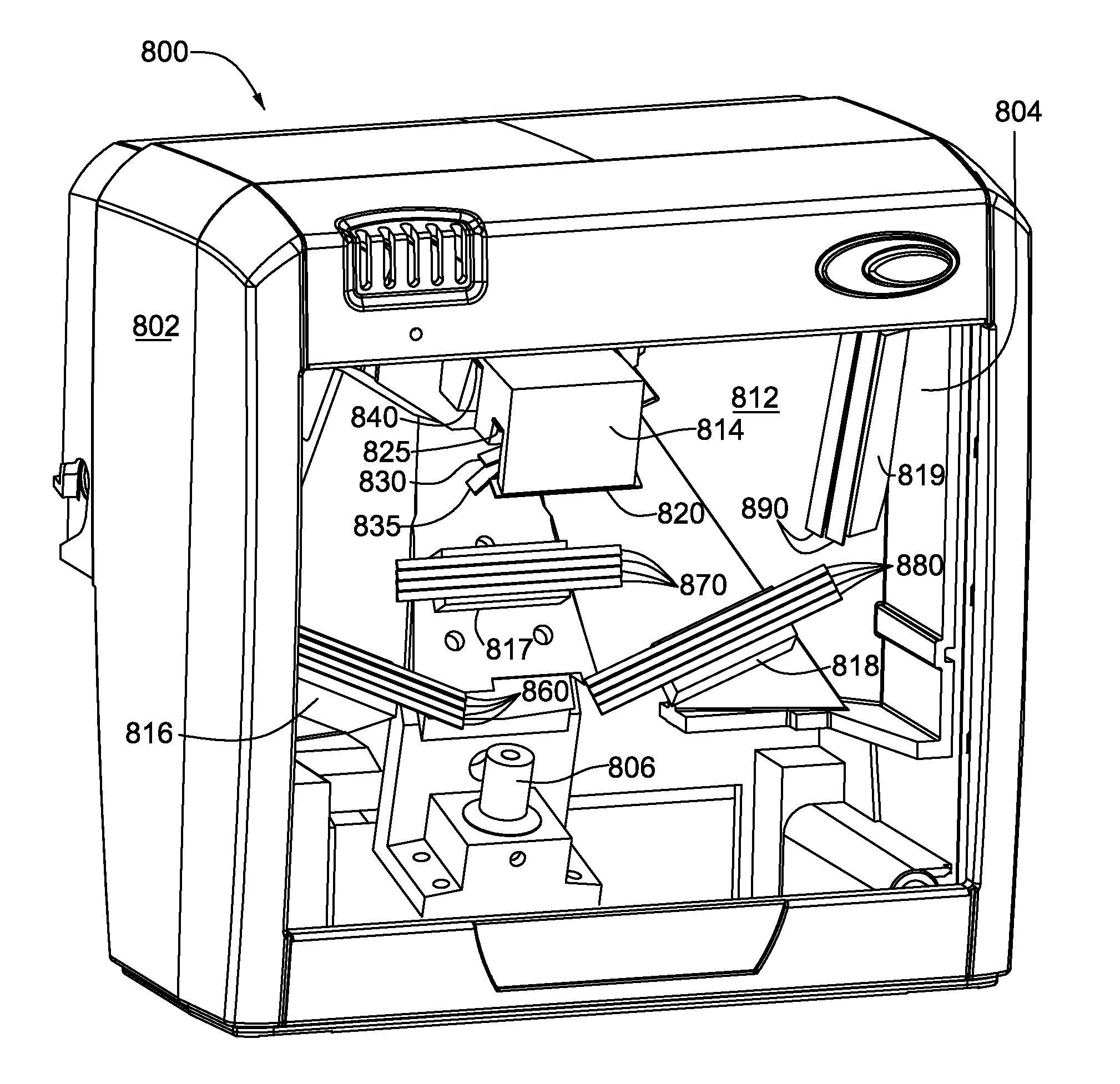
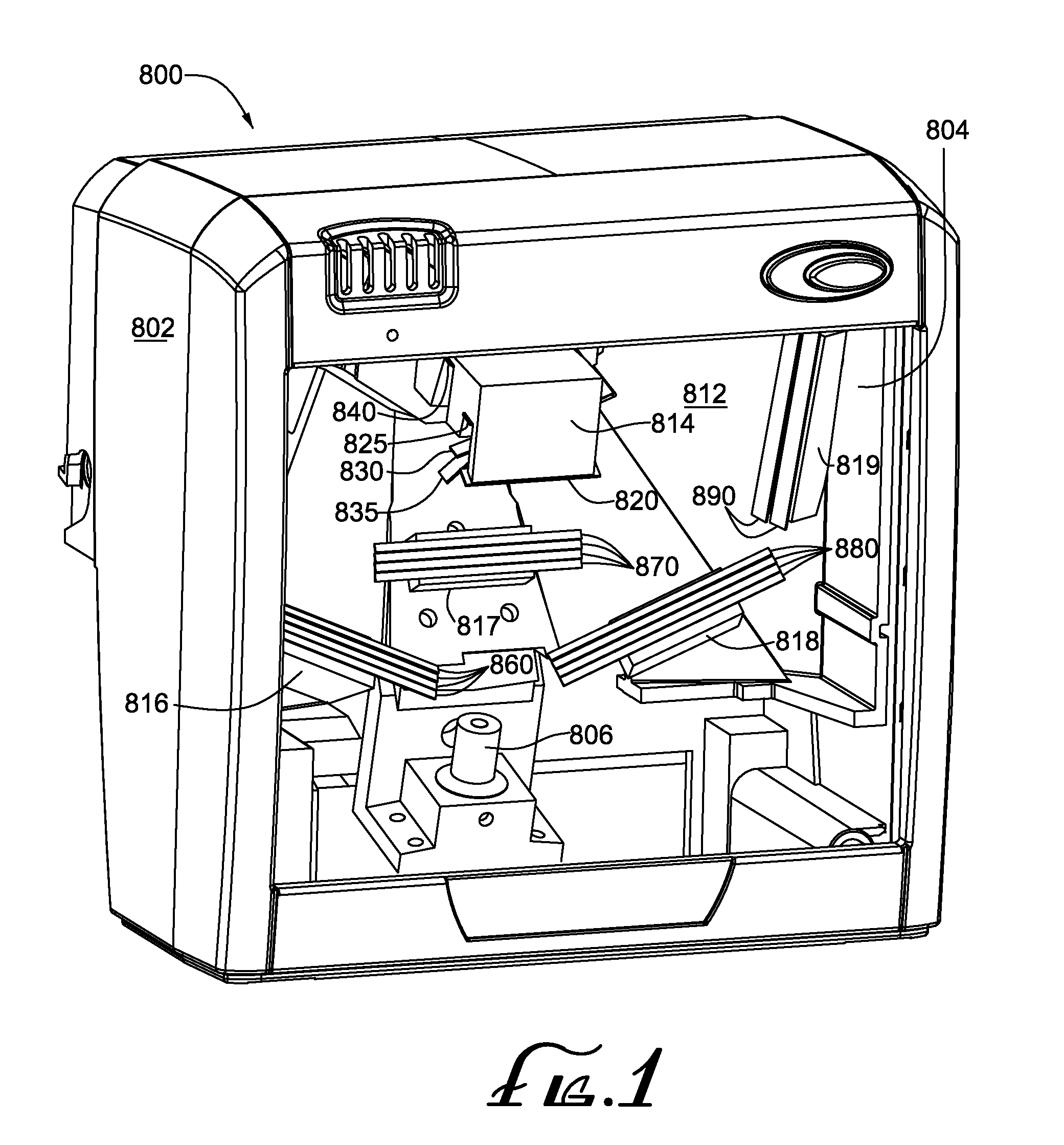
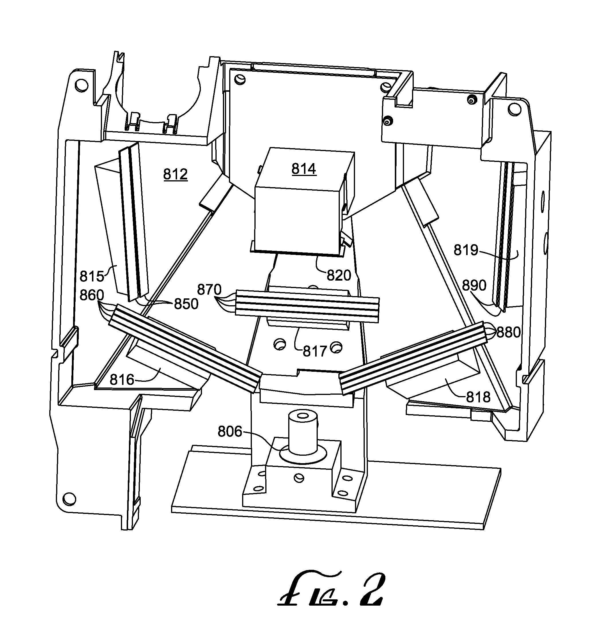
[0055]With reference to the above-listed drawings, this section describes particular embodiments and their detailed construction and operation. The embodiments described herein are set forth by way of illustration only and not limitation. Those skilled in the art will recognize in light of the teachings herein that other embodiments are possible, variations can be made to the embodiments described herein, and there may be equivalents to the components, parts, or steps that make up the described embodiments. For example, while the example embodiments described herein are principally fixed scanners, the teachings herein are equally applicable to presentation or handheld scanners.

[0056]For the sake of clarity and conciseness, certain aspects of components or steps of certain embodiments are presented without undue detail where such detail would be apparent to those skilled in the art in light of the teachings herein and / or where such detail would obfuscate an understanding of more pert...


PUM


Abstract

A monolithic compound mirror structure is used in an optical code reader employing an imager that captures images of items bearing optical codes in a viewing volume of the optical code reader. The monolithic compound mirror structure comprises a plurality of highly reflective surfaces positioned on the structure so that the structure can be positioned in a field of view of the imager in the optical code reader and oriented so that two or more of the plurality of highly reflective surfaces appear in the field of view of the imager, to thereby split the field of view of the imager into two or more different views into the viewing volume. The different views into the viewing volume may be direct off of the monolithic compound mirror structure or indirect off of one or more intermediate mirrors.

Description

RELATED APPLICATIONS[0001]This application is a continuation-in-part of U.S. application Ser. No. 12 / 370,497, filed Feb. 12, 2009, entitled “Systems and Methods for Forming a Composite Image of Multiple Portions of an Object From Multiple Perspectives,” which claims priority under 35 U.S.C. §119 to (1) U.S. provisional application No. 61 / 028,164, filed Feb. 12, 2008, with the same title and (2) U.S. provisional application No. 61 / 140,930, filed Dec. 26, 2008, entitled “Optical Code Reader Having Compact Arrangement for Acquisition of Multiple Views of an Object.” This application also claims priority under 35 U.S.C. §119 to U.S. provisional application No. 61 / 140,930. The entire disclosures of the foregoing applications are incorporated by reference herein.[0002]The entire disclosures of the assignee's following U.S. patent applications filed on the same date as this application are also incorporated by reference herein: No. 12 / ______,______ (attorney docket no. 51306 / 1251) entitled...

Claims


Application Information

Patent Timeline
Patent Type & Authority Applications(United States)
IPC IPC(8): G06K7/10
CPCG06K7/10702G06K7/10861
Inventor OLMSTEAD, BRYAN L.
Owner DATALOGIC ADC
Why Eureka
Try Eureka