Self-powered sensor system for monitoring tire pressure

a self-powered, tire pressure sensor technology, applied in the direction of tire measurement, vehicle components, transportation and packaging, etc., can solve the problems of limited battery life, high cost, and large siz

Active Publication Date: 2010-07-01
STMICROELECTRONICS SRL
View PDF21 Cites 70 Cited by
  • Summary
  • Abstract
  • Description
  • Claims
  • Application Information

AI Technical Summary

Benefits of technology

[0011]A tire pressure sensor device measures the air pressure in an inflatable automobile tire according to one embodiment. The air pressure sensor device is located entirely within an inflatable portion of the tire. The sensor device is very small compared to the interior of the tire and is not attached to the tire wall or to the wheel, therefore the sensor freely moves about the inside of the tire when the tire is in motion.

Problems solved by technology

On-board, in-motion systems for monitoring tire pressure exist, but typically these systems suffer from problems such as limited battery life, large size, and high cost.
In systems that use a wired connection to power a tire-mounted sensor, there is the difficult problem of making a reliable continuous-path connection between the tire-mounted sensor and the chassis-mounted portion of the system.
Monitoring the pressure sensor in such a system may also be a problem for the same reason.
The sensors are typically quite large and are subject to damage during tire removal and fitting procedures.
Banded sensors may also damage the tire bead's air seal.
A disadvantage of these systems is that they are not as accurate and require frequent recalibration.
Of course, as the tire wears out, or if new tires of a different size are purchased, the system either needs to be recalibrated or is no longer sufficiently accurate to be useable.

Method used


Image

  • Self-powered sensor system for monitoring tire pressure
  • Self-powered sensor system for monitoring tire pressure
  • Self-powered sensor system for monitoring tire pressure

Examples


Embodiment Construction

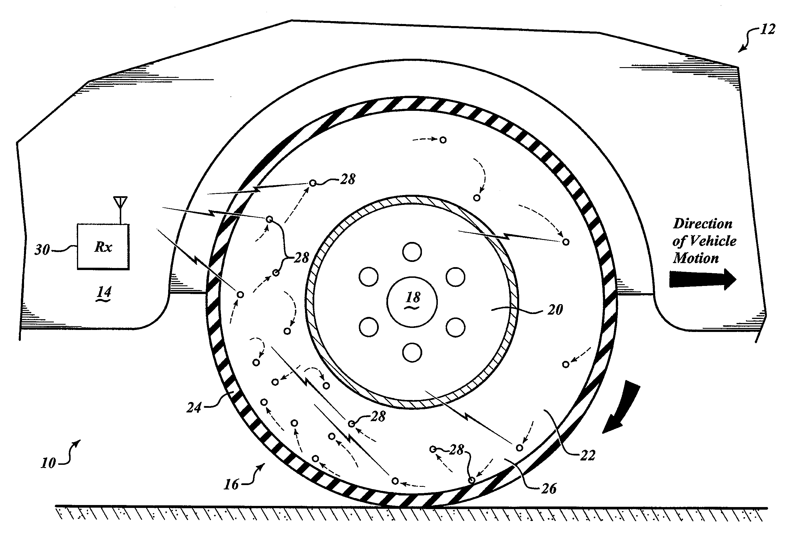
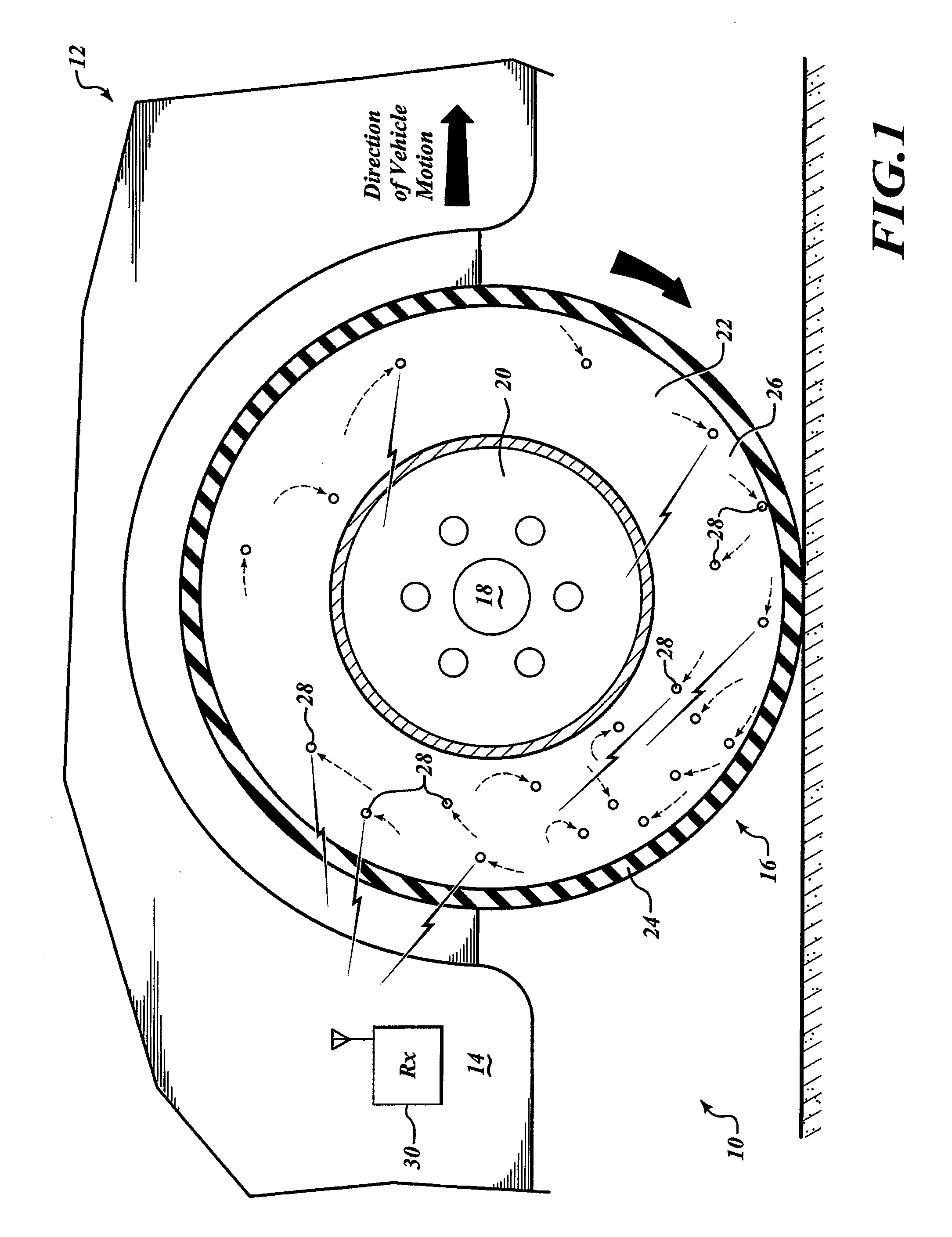
[0022]FIG. 1 shows a self-powered tire pressure sensor system 10 installed on a vehicle 12. The vehicle 12 includes a chassis 14, a wheel 16, and a hub 18. The wheel 16 is mounted to the hub 18 by structures well known in the art. The hub 18 is connected to the chassis 14 by structures well known in the art, to couple the wheel 16 to the chassis 14. The wheel 16 includes a rim 20 and a tire 22 thereon. The tire 22 includes a body portion 24 having a tread area and walls, and an inflatable interior portion 26. The inflatable portion 26 is defined by the tread area and walls of the body portion 24 and the rim 20 to which the tire 22 is mounted. FIG. 1 shows in a partial cut-away view the relation between the body portion 24 and the inflatable portion 26.

[0023]Within the inflatable portion 26 of the tire 22 are a plurality of integrated pressure sensor devices 28. The integrated pressure sensor devices 28 move freely about the inflatable portion 26 of the tire 22. Considering the direc...


PUM


Abstract

A self-powered tire pressure sensor device. The sensor device includes a power circuit, an air pressure measurement sensor, a signal circuit and a wireless transmission circuit. The power circuit converts mechanical acceleration experienced by the device into electrical potential using an electromechanical transducer. Mechanical acceleration due to collisions between the mobile sensor device and the wall of the tire while the tire is in motion cause the transducer to emit a small electrical charge. An electrical potential storage element in the power circuit accumulates and stores the charge as electrical potential. Alternatively the power circuit receives and converts electromagnetic energy into electrical potential. The electrical potential powers an air pressure measurement sensor within the tire. A signal circuit and wireless transmission circuit transmit the measurement to a chassis-mounted receiver, which makes the tire pressure measurement available to systems remote from the tire.

Description

BACKGROUND[0001]1. Technical Field[0002]This description generally relates to the field of automotive tire pressure sensors, and more particularly to sensors that provide the tire pressure while the automobile is being driven.[0003]2. Description of the Related Art[0004]The accurate measure of vehicle tire pressure while a vehicle is moving can prevent accidents and increase gas mileage. Government and university studies have cited the connection between tire under-inflation and vehicle crashes, including fatality rates.[0005]On-board, in-motion systems for monitoring tire pressure exist, but typically these systems suffer from problems such as limited battery life, large size, and high cost. In systems that use a wired connection to power a tire-mounted sensor, there is the difficult problem of making a reliable continuous-path connection between the tire-mounted sensor and the chassis-mounted portion of the system. Monitoring the pressure sensor in such a system may also be a prob...

Claims


Application Information

Patent Timeline
Patent Type & Authority Applications(United States)
IPC IPC(8): B60C23/02
CPCB60C23/041B60C23/0411B60C23/0413B60C23/0491
Inventor BLANCHARD, RICHARD AUSTIN
Owner STMICROELECTRONICS SRL
Why Eureka
Try Eureka