
System and method for feedback cancellation in repeaters

a repeater and feedback technology, applied in the field of system and attenuating feedback signals, can solve the problems of a very low signal reception area, a large base station, and a costly and large number of base stations, and achieve the isolation between the two opposing antennas or sets of antennas. performance-limiting characteristic of a repeater

Active Publication Date: 2010-07-01
COMMSCOPE TECH LLC
View PDF43 Cites 119 Cited by
  • Summary
  • Abstract
  • Description
  • Claims
  • Application Information

AI Technical Summary

Problems solved by technology

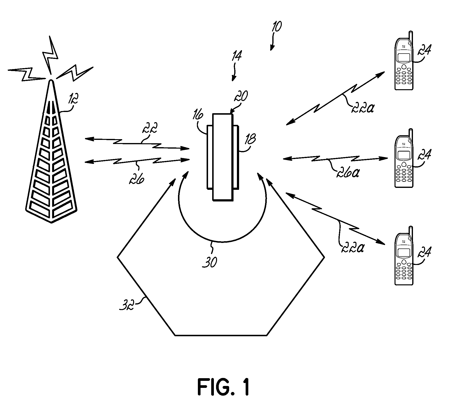
In such coverage areas, there are often smaller areas that have very low signal reception, such as areas within buildings or areas that are otherwise obstructed.
Rather than implementing another costly and large base station to provide coverage to such low signal areas, repeaters are utilized.
One performance-limiting characteristic for a repeater is the isolation between the two opposing antennas or sets of antennas.
However, such a technique for addressing feedback signals is not suitable for all repeaters.
As such, a time delay-based adaptive filtering algorithm is not able to distinguish sufficiently between the desired input signals, such as the downlink signals from the base station, and the undesired feedback signal between the transmit and receive antennas of the repeater.
Such an amount of delay could be too high, and could cause intra- or intersymbol interference that could not be tolerated by wireless devices, such as mobile phones, in various overlap areas where the wireless devices can receive signals at similar levels from both the base station and a repeater.
Accordingly, existing techniques in the art that incorporate time delays are unable to provide the necessary cancellation of feedback signals in a repeater system that support signals with a symbol period exceeding half of the repeater group delay.

Method used


Image

  • System and method for feedback cancellation in repeaters
  • System and method for feedback cancellation in repeaters
  • System and method for feedback cancellation in repeaters

Examples


Embodiment Construction

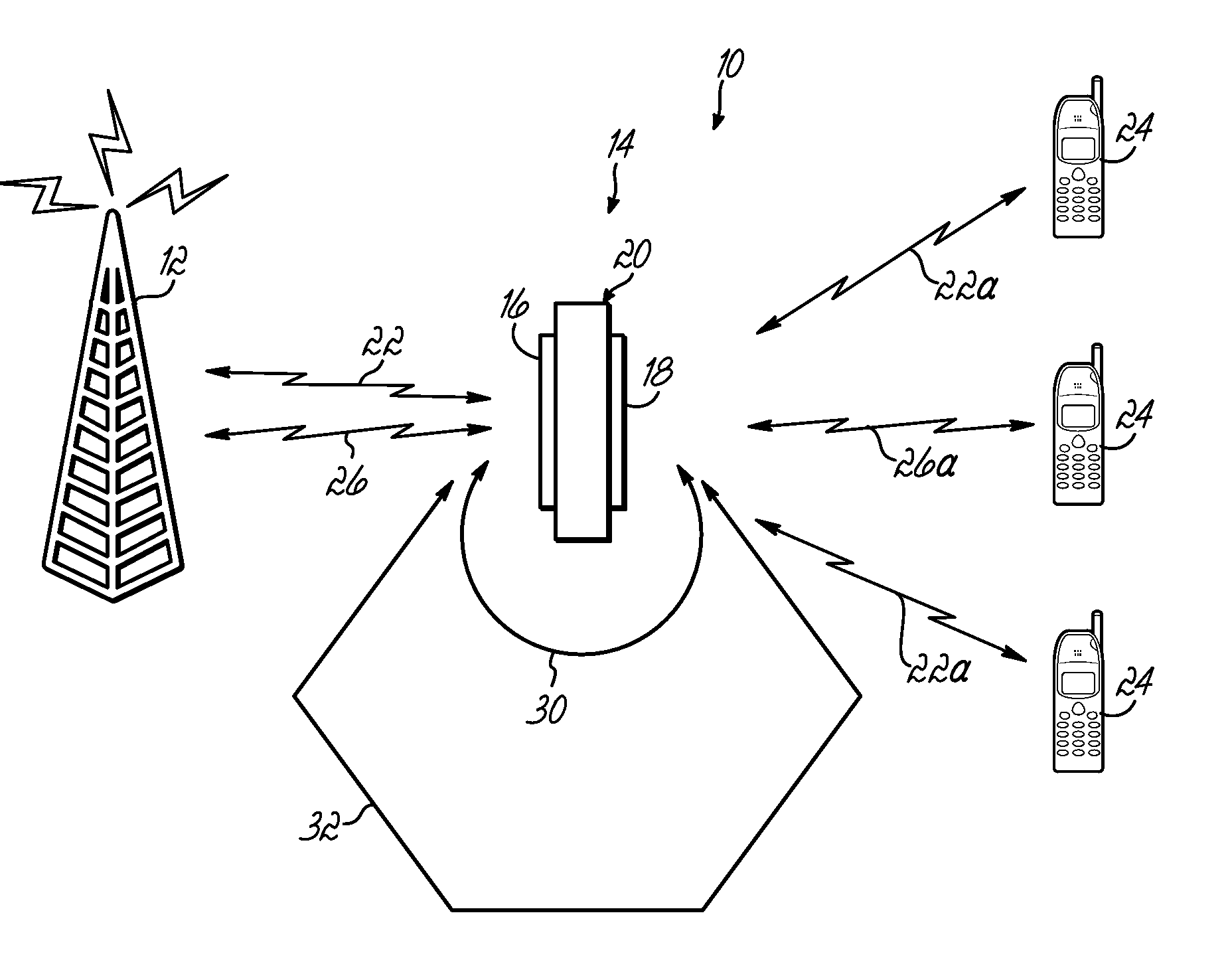
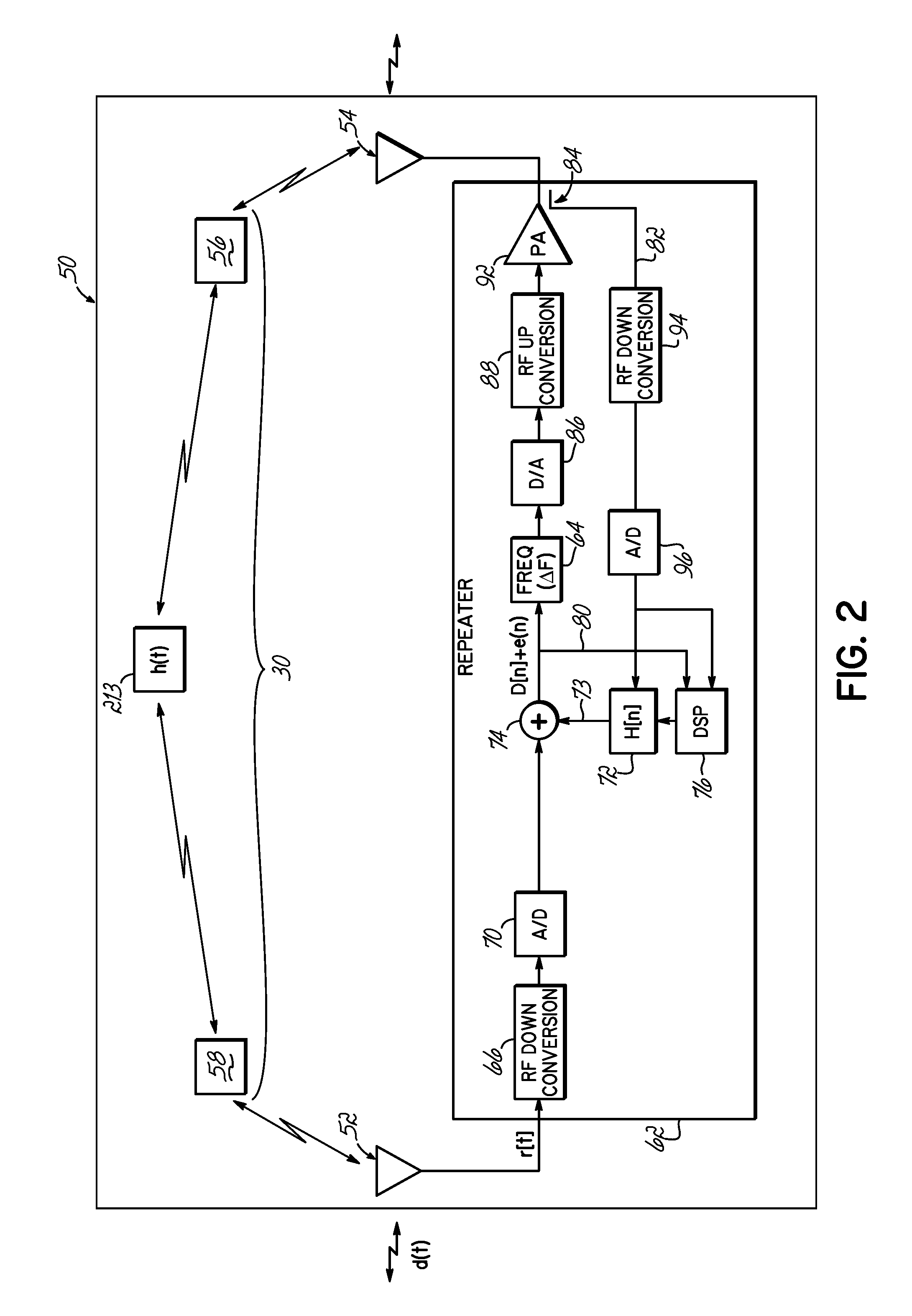
[0016]The present invention provides a signal repeating apparatus, or a repeater that provides attenuation of feedback signals received from the transmitter. Particularly, the inventive repeater more efficiently attenuates the feedback signals that are fed from the repeater's transmit antenna back to the receive antenna and consequently preventing the repeater from signal quality degradation or self-oscillation. Processing circuitry for processing input signals of the repeater to form transmission signals includes an adaptive digital filter that is configured to generate cancellation signals that are added to the input signals to cancel the unwanted signals, such as echo signals, from the input signals. The repeater, in one embodiment, uses a frequency shifting circuit to add a frequency shift and form transmission or repeated signals that are frequency shifted from the input signals originally received by the repeater. The digital signal processor that adapts the adaptive digital f...


PUM


Abstract

An apparatus for repeating signals includes a receive antenna for receiving input signals, processing circuitry for processing the input signals to form repeated signals, and a transmit antenna for transmitting the repeated signals. The processing circuitry includes an adaptive digital filter configured to generate cancellation signals that are added to the input signals to cancel unwanted feedback signals from the input signals. A frequency shifting circuit adds a frequency shift to the input signals, after the addition of the cancellation signals, to form repeated signals that are frequency shifted from the input signals. A digital signal processor is coupled to the adaptive digital filter for digitally adapting the filter. The digital signal processor utilizes the frequency shift of the transmission signals to adapt the adaptive digital filter.

Description

FIELD OF THE INVENTION [0001]The present invention is directed generally to repeaters or signal repeating devices for wireless communications, and more particularly to an apparatus and method for attenuating feedback signals received from the transmitter's output.BACKGROUND OF THE INVENTION [0002]In existing wireless technologies, signal repeating devices, or “repeaters” are used to extend the coverage of the overall wireless system. For example, often such systems consist of a plurality of base stations that communicate with each other and operate to provide a defined coverage area. In such coverage areas, there are often smaller areas that have very low signal reception, such as areas within buildings or areas that are otherwise obstructed. Rather than implementing another costly and large base station to provide coverage to such low signal areas, repeaters are utilized. A repeater essentially has a donor antenna that is in communication with one or more base stations. The repeate...

Claims


Application Information

Patent Timeline
IPC IPC(8): H04B7/14
CPCH04B7/15571H04B7/15
Inventor RANSON, CHRISHANSON, VANKUMMETZ, THOMAS
Owner COMMSCOPE TECH LLC
Learn More