Turbo chiller, heat source system, and methods for controlling them

a technology of heat source system and chiller, which is applied in the direction of nuclear elements, instruments, lighting and heating apparatus, etc., can solve the problems of huge amount of data, unrealistic, and inability to operate at high efficiency of chiller, and achieve energy-saving operation, high coefficient of performance, and adequate chilling capacity range

Active Publication Date: 2010-07-08
MITSUBISHI HEAVY IND LTD
View PDF1 Cites 22 Cited by
  • Summary
  • Abstract
  • Description
  • Claims
  • Application Information

AI Technical Summary

Benefits of technology

[0020]According to the invention, substituting a head at the time of operation into an arithmetic expression allows an adeq...

Problems solved by technology

At a cooling water temperature at which the relationship has not been obtained, the turbo chiller cannot be operated a...

Method used


Image

  • Turbo chiller, heat source system, and methods for controlling them
  • Turbo chiller, heat source system, and methods for controlling them
  • Turbo chiller, heat source system, and methods for controlling them

Examples


Embodiment Construction

[0035]An embodiment according to the invention will be described below with reference to the drawings.

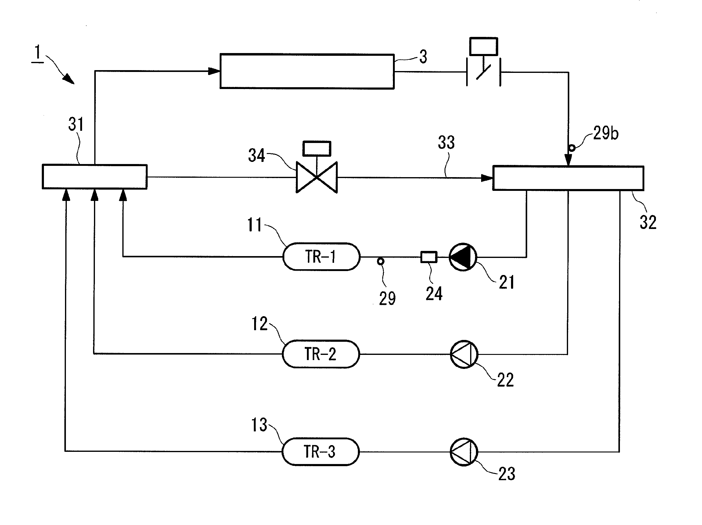
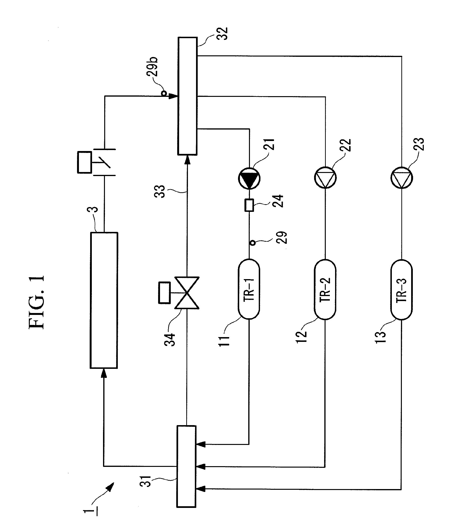
[0036]FIG. 1 shows an overall configuration of a heat source system according to an embodiment.

[0037]The heat source system 1 is installed in buildings and factory facilities. The heat source system 1 includes three turbo chillers, first to third turbo chillers 11, 12, and 13, each of which providing low-temperature heat to cooled water to be supplied to an external load 3, such as an air conditioner and a fan coil. The first to third turbo chillers 11, 12, and 13 are disposed in parallel to the external load 3.

[0038]First to third cooled water pumps 21, 22, and 23 that pump cooled water are provided upstream of the turbo chillers 11, 12, and 13, respectively, when viewed in the direction in which the cooled water flows. The cooled water pumps 21, 22, and 23 deliver cooled water from a return header 32 to the turbo chillers 11, 12, and 13. Each of the cooled water pumps 21, 22, and ...


PUM


Abstract

There is provided a turbo chiller that can be operated at high efficiency within an adequate chilling capacity range even when the cooling water temperature changes during the operation. The adequate chilling capacity range is obtained by using a flow coefficient and a pressure coefficient at a specific operating point of a turbo compressor as well as a predetermined coefficient to determine an arithmetic expression representing the relationship between a head and a chilling capacity, using a chilling capacity that can lead to a substantially highest coefficient of performance at a single head to obtain the predetermined coefficient as an optimum coefficient, computing an adequate operation coefficient range having a predetermined range and including the optimum coefficient, and substituting the adequate operation coefficient range and a head at the time of operation into the arithmetic expression.

Description

TECHNICAL FIELD[0001]The present invention relates to a turbo chiller, a heat source system, and methods for controlling them.BACKGROUND ART[0002]There is a heat source system using a plurality of turbo chillers. The heat source system controls the number of turbo chillers to be activated in accordance with the amount of heat required for an external load. In the number control, it is required to save energy by operating the activated turbo chillers at high efficiency.[0003]Patent Citation 1 discloses a technology for obtaining the relationship between the coefficient of performance and the load factor of an inverter-driven turbo chiller, the coefficient of performance determined by the temperature of cooling water supplied to a condenser, and controlling the inverter in such a way that the coefficient of performance is greater than or equal to a predetermined value.[0004]Patent Citation 1: Japanese Unexamined Patent Application, Publication No. 2005-114295DISCLOSURE OF INVENTION[00...

Claims


Application Information

Patent Timeline
IPC IPC(8): F25B27/00F25B1/00G05B15/00
CPCF04D27/0261F25B1/053F25B1/10F25B41/043F25B2400/13F25B2400/23F25B2500/19F25B2600/021Y02B30/741Y02B30/70F25B41/22
Inventor UEDA, KENJI
Owner MITSUBISHI HEAVY IND LTD
Why Eureka
Try Eureka