Apparatus for wearing a wig

a technology for wigs and wig clips, applied in the field of wig accessories, can solve the problems of pain, clipped hair pulling of wearers, and inability to freely attach or detach wigs, and achieve the effect of excellent fitness and no pain in the attaching/detaching operation

Inactive Publication Date: 2010-07-08
ADERANS HLDG CO LTD
View PDF29 Cites 7 Cited by
  • Summary
  • Abstract
  • Description
  • Claims
  • Application Information

AI Technical Summary

Benefits of technology

[0021]An apparatus for wearing a wig according to the present invention has a structure in which a plurality of monofilaments, each having a predetermined shape, flexibility, and size, are disposed on a base sheet in the form of projection, wherein a wig can surely be attached to the head of the wig wearer only by lightly pressing the wig, which is put on the head of the wig wearer, from above. Accordingly, the apparatus is suitable for an elderly person having weak finger strength or a person who cannot freely use his/her fingers. Further, the wig can be attached without being lifted up from the head of the wearer, whereby the apparatus is excellent in fitness, and does not cause pain in the attachin...

Problems solved by technology

However, according to the apparatus using inversion clip disclosed in the Patent Document 1, finger strength to some extent is necessary for inverting the inversion clip, and thus an elderly person having a weak finger strength or a person who cannot freely use his/her fingers cannot freely attach or detach a wig by himself/herself.
Further, the apparatus entails a problem that the clipped hairs of the wearer are pulled since the inversion clip clips the natural hairs of the wearer, by which the wearer feels pain.
Therefore, this device has weak fixing ...

Method used


Image

  • Apparatus for wearing a wig
  • Apparatus for wearing a wig
  • Apparatus for wearing a wig

Examples


examples

[0052]Four Examples and nine Comparative Examples were prepared for the apparatus for wearing a wig 20, and a test for attaching and detaching the wig 26 to and from the head of the wearer was conducted with these apparatuses. The manner of the test is as follows. Specifically, the wig 26 was actually attached and detached to evaluate the practicability, and the flexibility of the monofilaments 22 and the peeling force of the apparatus for wearing a wig 20 in detaching the wig 26 were measured by a tester. The peeling force corresponds to the fixing strength in the vertical direction caused by the entanglement between the monofilaments 22 of the apparatus for wearing a wig 20 or the hook between the monofilaments 22 and the natural hairs of the wig wearer, i.e., the hooking force. The fixing strength in the horizontal direction caused by the entanglement between the monofilaments 22 of the apparatus for wearing a wig 20 or the hook between the monofilaments 22 and the natural hairs ...

examples 1 and 2

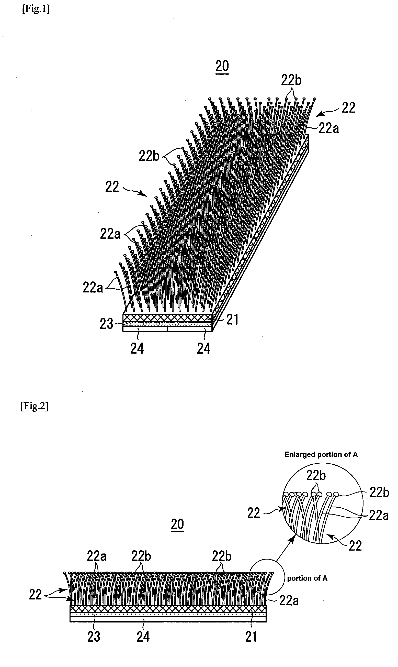
[0053]The conditions described below were set for the apparatus for wearing a wig 20 used in Example 1.[0054]Base sheet 5: A sheet made of synthetic resin, having a rectangular shape of 1.5 cm×3.5 cm with thickness of 0.5 mm[0055]Arrangement of monofilaments 22: Irregularly[0056]Film covering monofilament 22: Provided (10 μm)[0057]Diameter of stalk 22a of monofilament 22: 0.3 mm[0058]Height of stalk 22a of monofilament 22: 4 mm[0059]Diameter of head 22b of monofilament 22: 0.5 mm[0060]Disposal density of monofilaments 22: 80 pieces / cm2

[0061]The apparatus for wearing a wig 20 used in Example 2 was the same as that of Example 1 except that the monofilaments 22 were aligned.

examples 3 and 4

[0063]The apparatus for wearing a wig 20 used in Example 3 was the same as that of Example 1 except that the film was absent. The apparatus for wearing a wig 20 used in Example 4 was the same as that of Example 2 except that the film was absent.


PUM


Abstract

Objects of the present invention is to provide a wig capable of surely and easily being attached only by lightly pressing a wig, which is put on a head of a wearer, from above; to enhance fitness; and to cause no pain in the attaching or detaching operation or while long-time use. A plurality of monofilaments 22, which get entangled and hooked with natural hair of the wearer, are provided in the form of projection on a first side of a base sheet 21, and an adhesive layer 23 for bonding to the inside of the wig base is applied on a second side of the base sheet 21. Each of the monofilaments 22 is composed of a stalk 22a extending from the base sheet 21 and a big head 22b on the top of the stalk 22a. In attaching the wig to the head of the wearer, the monofilaments 22 are deflected by an external pressing force so as to get entangled and hooked with each other, and the natural hair of the wearer gets entangled with the stalk 22a or the head 22b of the monofilaments 22, whereby this state of the entanglement is kept to fix the wig onto the head.

Description

TECHNICAL FIELD[0001]The present invention relates to an apparatus for wearing a wig that is bonded to the inside of a wig base, to which imitation hairs such as artificial hairs or human hairs are implanted, for easily and surely wearing a wig on a head of a wearer.BACKGROUND ART[0002]The followings have been known, as an apparatus for mounting head accessories, such as a wig, a hat and a hair band, onto a head of a wearer. An inversion clip that is made of a metal or synthetic resin and fixed to the inside of a wig base, wherein the inversion clip is so bent as to hold the hairs of a wig wearer with teeth of the inversion clip (Patent Document 1); an apparatus on a back surface of a hair band having a structure, like a male sheet of a hook-and-loop fastener, in which a great number of monofilaments are disposed on a base sheet in the form of projection as an anti-slip tape (Patent Document 2); an apparatus having an head accessory put on a head such as a wig or a hat and a band-li...

Claims


Application Information

Patent Timeline
IPC IPC(8): A41G3/00
CPCA41G5/006A41G3/0008A41G3/0083A41G5/0013
Inventor KIMURA, HARUMI
Owner ADERANS HLDG CO LTD
Why Eureka
Try Eureka