Telescoping foldable chair

Inactive Publication Date: 2010-07-08
CHEN LIBIN
View PDF5 Cites 54 Cited by
  • Summary
  • Abstract
  • Description
  • Claims
  • Application Information

AI Technical Summary

Benefits of technology

[0005]The main object of the invention is to provide a telescoping

Problems solved by technology

This foldable chair 9 has some drawbacks: a volume of the foldable chair is large and a operatio

Method used


Image

  • Telescoping foldable chair
  • Telescoping foldable chair
  • Telescoping foldable chair

Examples


Embodiment Construction

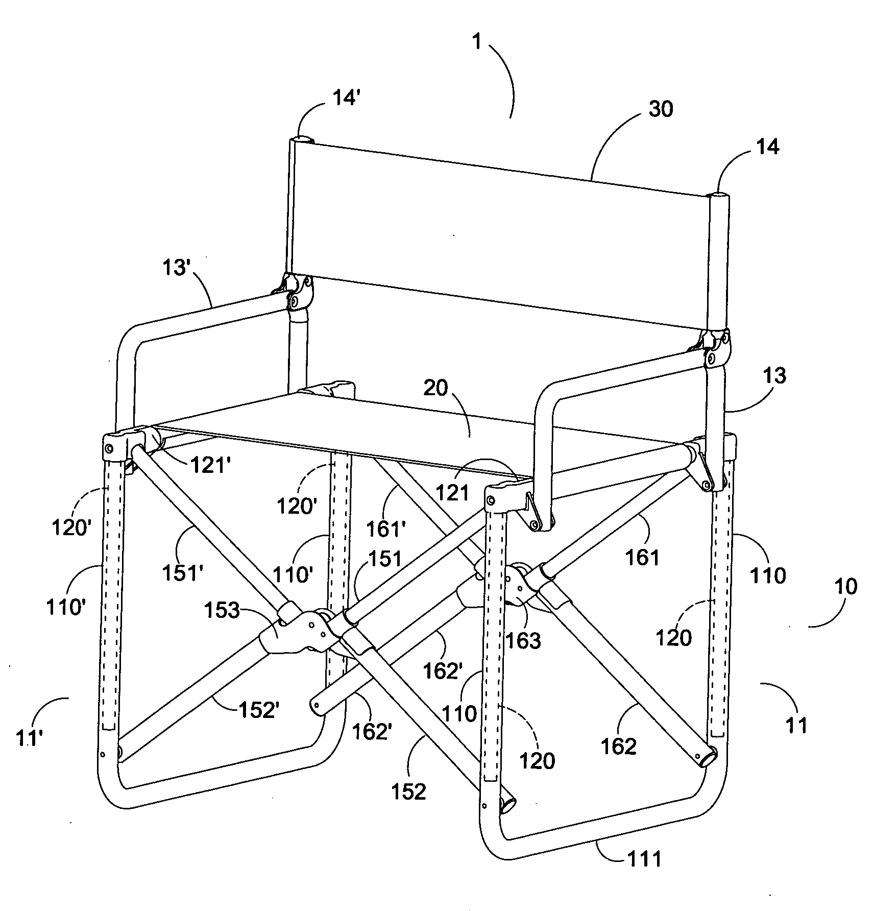
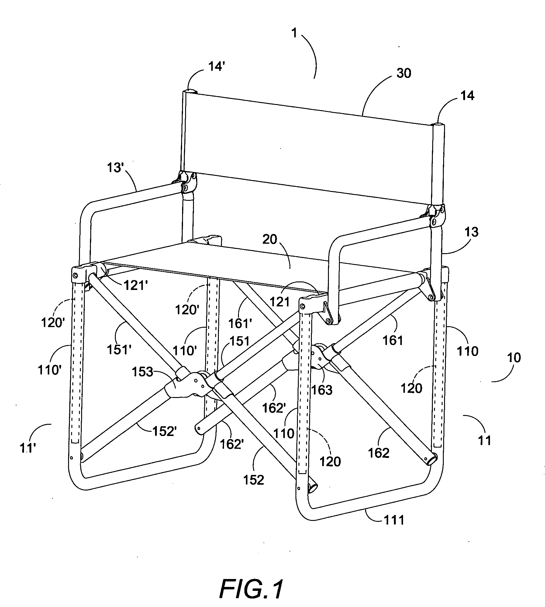
[0013]As shown in FIG. 1, a preferred embodiment of a telescoping foldable chair 1 of the invention has a skeleton 10, a soft yet strong sitting cloth 20 attached on the skeleton 10, and a soft yet strong back cloth 30 attached on the skeleton 10.

[0014]The skeleton 10 has a pair of lower leg frames 11, 11′ of U shape and each having a pair of outer legs 110, 110′ connected with a ground bar 111, 111′, a pair of upper leg frames 12, 12′ of inverted U shape and each having a pair of inner legs 120, 120′ connected with a top cross bar 121, 121′ and respectively slidably contained in an outer leg 110, 110′, a pair of arm frames 13, 13′ rotatably and respectively linked to the upper leg frames 12, 12′ with a pair of pins 122, a pair of back frames 14, 14′ rotatably and respectively linked to the arm frames 13, 13′. The back cloth 30 is attached to the pair of back frames 14, 14′ of the skeleton 10.

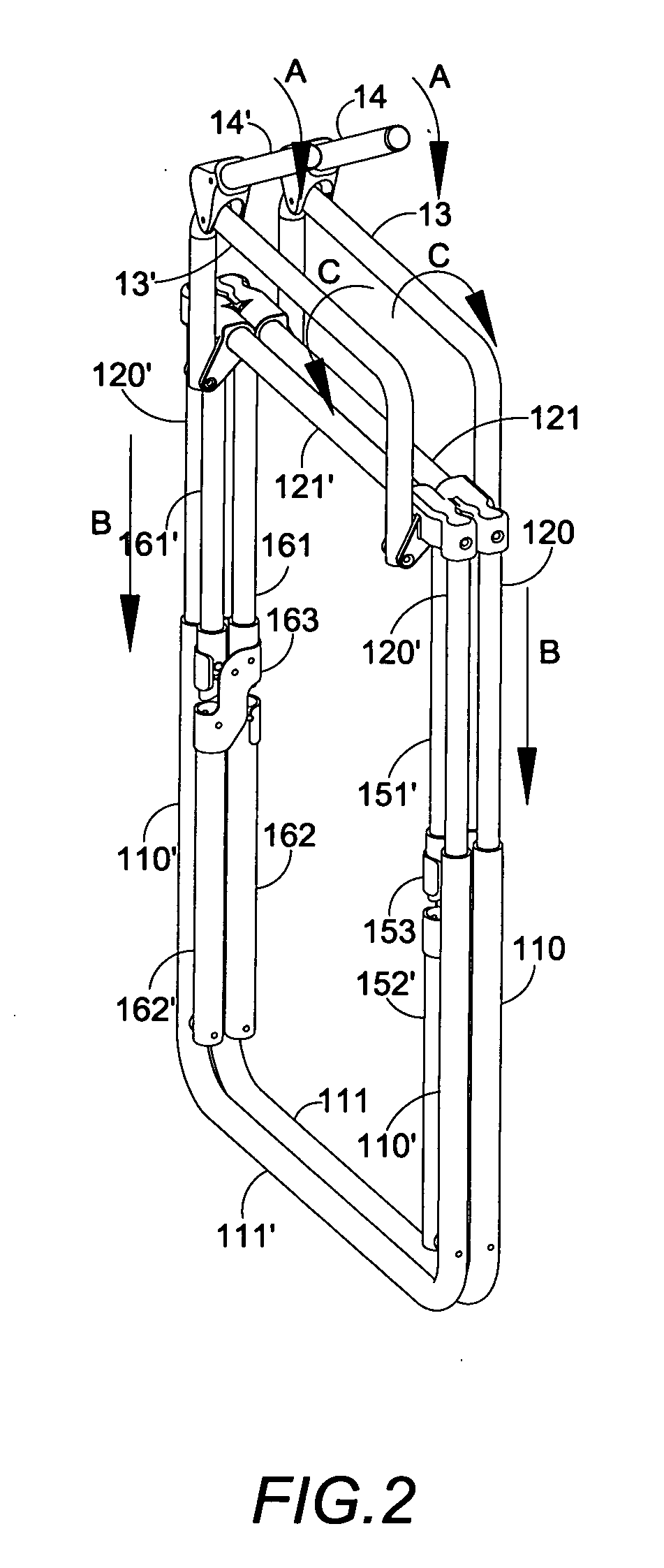
[0015]The pair of lower leg frames 11, 11′ and upper leg frames 12, 12′ are pivotally linke...


PUM


Abstract

A telescoping foldable chair having a skeleton having a pair of lower leg frames of U shape each having a pair of outer legs connected with a ground bar, a pair of upper leg frames of inverted U shape each having a pair of inner legs connected with a top cross bar respectively slidable contained in one of the outer legs, a front and a rear sets each having a pair of inner tubes respectively pivotally linked to the top cross bars, a pair of outer tubes respectively pivotally linked to one lower end of the outer leg frames, and a central link which pivotally connects free ends of the inner and outer tubes, and, a sitting cloth attached on the skeleton. The telescoping foldable chair has a strong structure yet small folded volume.

Description

BACKGROUND OF THE INVENTION[0001]1. Field of the Invention[0002]The invention relates to a telescoping foldable chair, and more particularly, to a foldable chair which has a strong structure and small folded volume.[0003]2. Description of the Prior Art[0004]Shown in FIGS. 4 and 5 is a conventional foldable chair 9. The foldable chair 9 has a skeleton 91, a sitting cloth 92 attached thereto, and a back cloth 93 attached thereto. The foldable chair 9 has a plurality of linking poles 94 which is used to make the non-telescoping bars of the skeleton 91 foldable with respect to each other. This foldable chair 9 has some drawbacks: a volume of the foldable chair is large and a operation of folding and expanding may be dangerous since the linking poles 94 may nip fingers of a user. A smaller folded volume of foldable chair is favorite. But a smaller volume usually means less structure tubes of chair skeleton. Therefore, a foldable chair having relatively more constructive skeleton tubes th...

Claims


Application Information

Patent Timeline
IPC IPC(8): A47C4/28
CPCA47C4/283A47C4/42
Inventor CHEN, LIBIN
Owner CHEN LIBIN
Why Eureka
Try Eureka