

Two-dimensional electric scanning lens antenna
A technology of lens antenna and electronic scanning, applied in the direction of antenna, electrical components, etc., can solve the problems of reducing structural firmness and compactness, reducing reflection, etc.
Inactive Publication Date: 2010-06-23
SOUTHEAST UNIV
View PDF0 Cites 28 Cited by
- Summary
- Abstract
- Description
- Claims
- Application Information
AI Technical Summary
Problems solved by technology
In order to make the polarization direction of the electromagnetic wave perpendicular to the conductor plate of the unit and reduce the reflection, a polarization rotator (Polarization Rotator-PR) needs to be added between the two ferroelectric lenses, and the ferroelectric lens and the pole The rotator usually needs to leave a gap, which reduces the firmness and compactness of the structure
Method used
View moreImage
Smart ImageViewing Examples

Examples
Embodiment 1
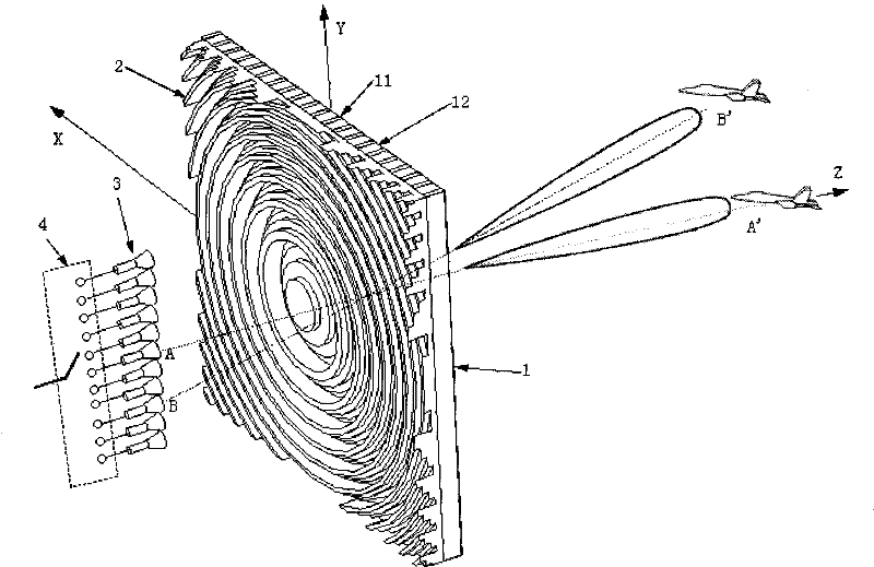
[0015] Example 1: The feed line array adopts a pyramidal horn array. Taking an 8×1 feed array as an example, a single-pole 8-throw PIN switch is connected behind it. Assuming that the input and output of the switch adopt a coaxial interface, the waveguide of the horn is passed through the waveguide together. A shaft converter is connected to the switch. With the help of an electronic control circuit for channel selection, electronic scanning can be realized. If there are more feed sources, taking 16 feed sources as an example, you can connect two single-pole 8-throw switches behind a single-pole double-throw switch to form a 1-way to 16-way switch, plus the corresponding control circuit. Electronic scanning can be done.
Login to View More PUM
 Abstract
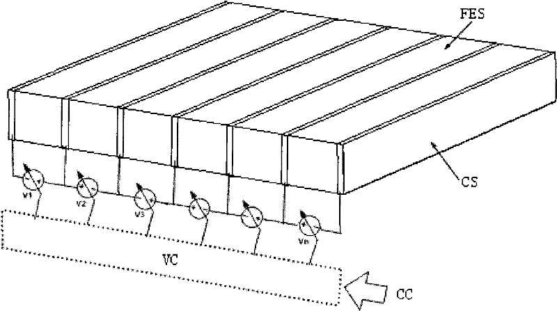
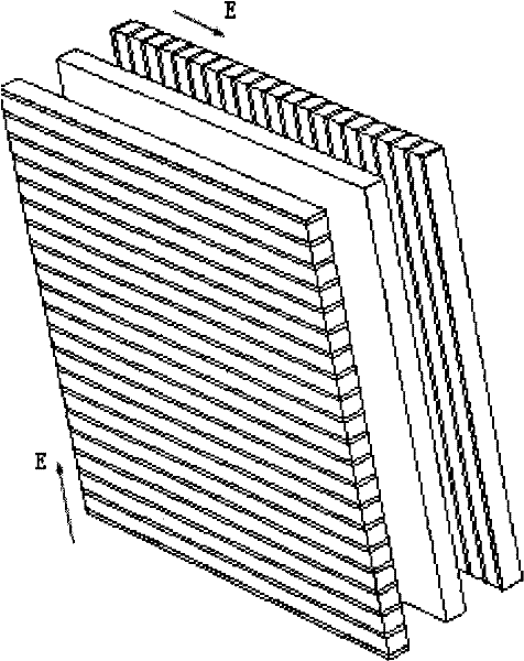
The invention provides a two-dimensional electric scanning lens antenna which has stable and compact structure and is used for scanning radar. The antenna comprises a ferroelectric lens antenna and a one-dimensional linear array feed source, wherein the ferroelectric lens antenna comprises conductor plane plates, ferroelectric dielectric plates are clamped among adjoining conductor plane plates, the ferroelectric lens antenna is provide with a binary diffraction lens, the binary diffraction lens is positioned between the one-dimensional linear array feed source and the ferroelectric lens antenna, the one-dimensional linear array feed source is connected with a N channels selecting switch, and the polarization direction of an electromagnetic wave which is transmitted or received by the one-dimensional linear array feed source is perpendicular to the direction of the long edges of the conductor plane plates. The antenna realizes the two-dimensional electric scanning through the N channels selecting switch and an N voltages control system; and compared with a scanning system which consists of two pieces of PELs, a scanning control part is simpler. A BDL is a plane structure, thereby not only effectively reducing the weight and the profile of the antenna, but also being capable of being wirelessly connected with an FEL of the plane structure, and being good for obtaining a stable and compact structure.
Description
1. Technical field: [0001] The invention relates to a two-dimensional electronic scanning lens antenna for scanning radar. 2. Background technology [0002] In the radar system, the scanning method of the antenna beam can be divided into two types: mechanical scanning and electronic scanning. Compared with the mechanical scanning antenna, the electronic scanning speed blocks, and the beam agility can be realized through computer control. The most common form of electronically scanned antenna is a phased array antenna, which is composed of many radiating elements, and each radiating element is connected with a phase shifter. The signals received by all radiating elements are beam-combined to form a receiving beam, and the space For detection in a certain direction, the direction of the receiving beam can be changed by controlling the phase shift amount of the phase shifter to realize two-dimensional electronically controlled scanning of the space. The use of a large number o...
Claims
Login to View More Application Information
Patent Timeline
 IPC IPC(8): H01Q3/46
Inventor王宗新尤立志
OwnerSOUTHEAST UNIV