Composite overfilled arch system

a composite, overfilled technology, applied in arch-type bridges, sewer pipelines, bridges, etc., can solve the problems of insufficient soil to support concentrated loads, restricted arch radius in practice, and loss of height lhb>1/, so as to improve advantages, efficient and effective housing

Inactive Publication Date: 2007-12-11
CONTECH ENGINEERED SOLUTIONS
View PDF34 Cites 32 Cited by
  • Summary
  • Abstract
  • Description
  • Claims
  • Application Information

AI Technical Summary

Benefits of technology

[0036]It is another object of the present invention to provide an overfilled arch which retains many of the advantages associated with cast-in-place overfilled bridge structures while eliminating, or at least substantially reducing, many of the disadvantages associated with a cast-in-place overfilled bridge structure.
[0037]It is another object of the present invention to further improve the advantages realized by the technology disclosed and taught in the referenced co-pending patent application.
[0038]These, and other, objects are achieved by an overfilled bridge arch that includes both precast and cast-in-place layers. The overfilled bridge arch can also be prestressed in an efficient and effective manner, or the ends of the arch arranged in such a way, such that bending moments induced by loading are efficiently and effectively accommodated and sensitivity of the arch to arch footing outward displacement is also reduced.
[003...

Problems solved by technology

Such soil is not adequate to support the concentrated loads at the ends of a flat arch or conventional arch without load distribution through the use of arch footings and/or reinforced foundation blocks.
Furthermore, as it is necessary to limit the normal forces and bending actions in the top and sides of prior art overfilled arch systems to an acceptable level, the radius of the arch is in practice restricted.
This results in a lost height LH1 and LH2 which can be substantial in some cases.
Arches, despite their economical advantage, often cannot compete with structures using beams or slabs for this reason, especially for larger spans.
However, the larger thickness may result in an expensive structure whose precast elements may be difficult, unwieldy and heavy to transport to a building site.
For overfilled arches made of precast c...

Method used


Image

  • Composite overfilled arch system
  • Composite overfilled arch system
  • Composite overfilled arch system

Examples


Embodiment Construction

[0061]Other objects, features and advantages of the invention will become apparent from a consideration of the following detailed description and the accompanying drawings.

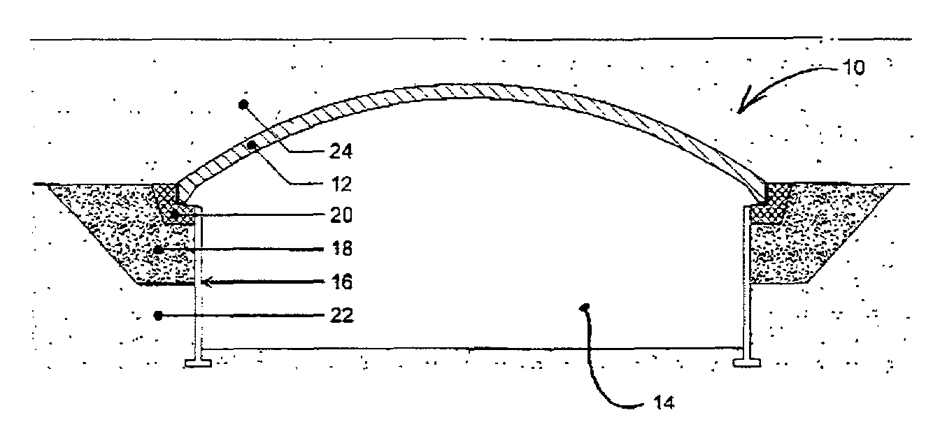
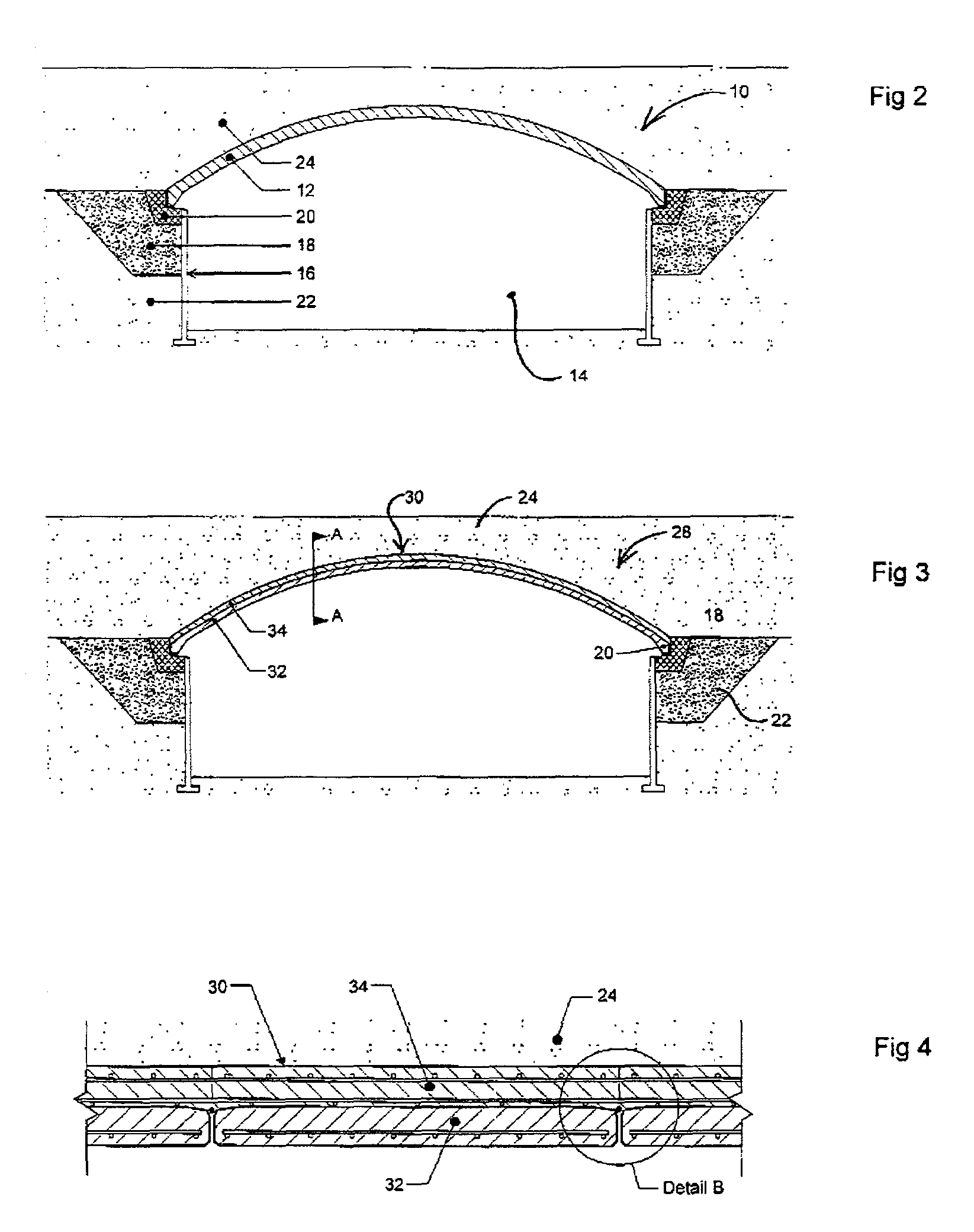
[0062]Broadly, the overfilled arch bridge structure and the elements thereof embodying the present invention can be independently used or used in conjunction with the overfilled bridge disclosed in the referenced co-pending patent application. While the present invention will be disclosed in combination with that structure, it should be understood that the present invention can be used independently of such structure and no limitation is intended by the disclosure of this invention in combination with the invention disclosed in the referenced co-pending patent application. The basic structure disclosed in the referenced patent application is shown in FIG. 2 as structure 10. As disclosed in the referenced co-pending patent application, earth overfilled arched structure 10 includes a shallow arch 12, which is concre...


PUM


Abstract

An overfilled arch bridge system includes a composite arch which has a precast layer and a cast-in-place layer. The system further includes means for reducing bending moments within the overfilled arch. The means include customizing the arch end geometry and prestressing the arch prior to or during loading. The system can be used in connection with the overfilled arch system disclosed in co-pending patent application titled “Top Arch Overfilled System” filed by the same inventor on Mar. 22, 2002.

Description

TECHNICAL FIELD OF THE INVENTION[0001]The present invention relates to the general art of structural, bridge and geotechnical engineering, and to the particular field of overfilled arch and / or cut-and-cover structures.CROSS-REFERENCE TO RELATED APPLICATIONS[0002]The present application incorporates by reference the disclosure of co-pending patent application titled “Top Arch Overfilled System” filed by the same inventor on Mar. 22, 2002.BACKGROUND OF THE INVENTION[0003]Frequently, overfilled arch structures formed of precast or cast-in-place reinforced concrete are used in the case of bridges to support one pathway over a second pathway, which can be a waterway, a traffic route, or in the case of other structures, a storage space of the like. The terms “overfilled arch” or “overfilled bridge” will be understood from the teaching of the present disclosure, and in general as used herein, an overfilled bridge or an overfilled arch is a bridge formed of arch elements that rest on the gr...

Claims


Application Information

Patent Timeline
IPC IPC(8): E04B1/32E01F5/00
CPCE02D29/05E01D4/00
Inventor HEIERLI, WERNER
Owner CONTECH ENGINEERED SOLUTIONS
Why Eureka
Try Eureka