MEMS dosimeter

Inactive Publication Date: 2010-07-08
CHARLES STARK DRAPER LABORATORY
View PDF36 Cites 15 Cited by
  • Summary
  • Abstract
  • Description
  • Claims
  • Application Information

AI Technical Summary

Benefits of technology

[0006]In various embodiments, the present invention features a small, disposable MEMS dosimeter that accurately records and electrically reads out the peak blast pressure and/or acceleration experienced by the dosimeter, and that is low enough in cost to be universally deployed. In one embodiment, the MEMS dosimeter is a passive chip in the sense that no battery, other power source, microprocessor, or digital memory is present on the chip. Adv

Problems solved by technology

Moreover, because the MEMS dosimeters require no battery or other p

Method used


Image

  • MEMS dosimeter
  • MEMS dosimeter
  • MEMS dosimeter

Examples


Example

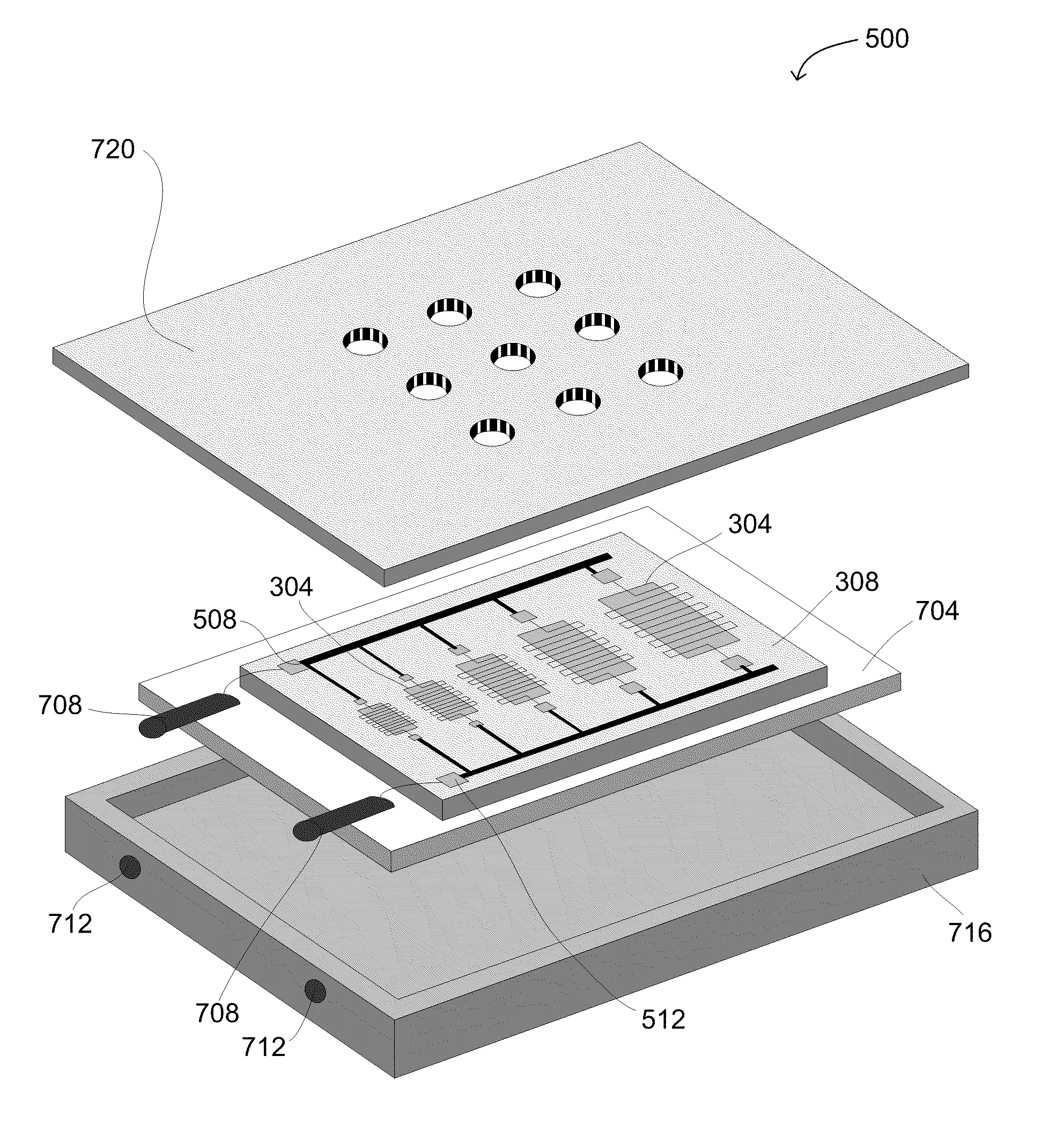
[0035]In various embodiments, the present invention features a MEMS dosimeter having a set of breakable structures, for example membranes or cantilevers that burst at well defined pressures or accelerations, respectively. This MEMS dosimeter need not include any batteries, other power sources, microprocessors, digital memories, or other active elements. Rather, in one embodiment, the MEMS dosimeter passively records a peak blast pressure or acceleration that it experiences, for example through a physical breakage of a select number of the membranes or cantilevers. As further described below, this peak blast pressure or acceleration may later be read out of the dosimeter (e.g., electrically read out) for various purposes (e.g., to rapidly measure and record the peak blast pressure experienced by a soldier, a construction worker, a miner, etc. to aid in the immediate treatment thereof, to conduct epidemiological studies, etc.).

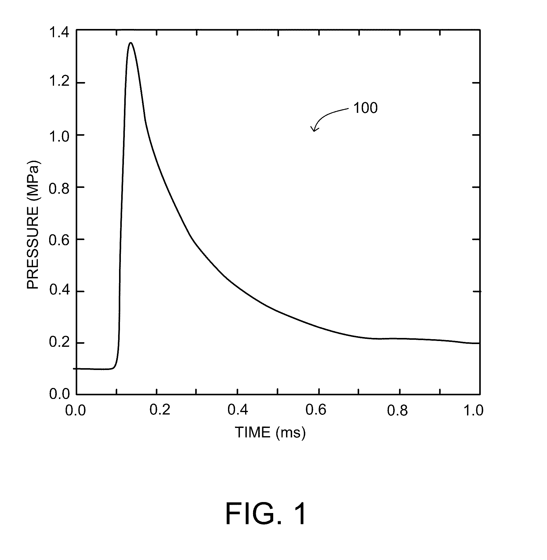
[0036]FIG. 1 depicts a pressure waveform 100 from an IED a...


PUM


Abstract

In various embodiments, a dosimeter is employed to passively record a peak pressure (e.g., a peak blast pressure) and/or a maximum acceleration experienced by the dosimeter.

Description

CROSS-REFERENCE TO RELATED APPLICATION[0001]This application claims priority to and the benefit of, and incorporates herein by reference in its entirety, U.S. Provisional Patent Application No. 61 / 112,563, which was filed on Nov. 7, 2008.TECHNICAL FIELD[0002]In various embodiments, the present invention relates to a micro-electro-mechanical systems (“MEMS”) dosimeter that passively records and reads out (e.g., electrically) a peak pressure (e.g., a peak blast pressure) and / or a maximum acceleration exposure.BACKGROUND[0003]Humans may experience high-pressure blasts in a variety of different contexts. For example, in military warfare, the increasing use of improvised explosive devices (“IEDs”) has made traumatic brain injury (“TBI”) a serious, hard-to-diagnose, and widespread injury. In addition to soldiers, however, other individuals who also work with explosives (e.g., construction workers, miners, etc.) may likewise experience a degree of high-pressure blasts, sometimes serious en...

Claims


Application Information

Patent Timeline
IPC IPC(8): G01R27/28H01L29/84G01P15/08
CPCA61B2562/028F41H1/02F41H1/04F42D5/00F42D5/04G01L5/14G01L9/0042G01L15/00G01P15/135H01H1/0036H01H35/146H01H35/2657G01P15/00G01N27/04
Inventor BERNSTEIN, JONATHAN J.
Owner CHARLES STARK DRAPER LABORATORY
Why Eureka
Try Eureka