
Multiple arm articulating mounting system

Inactive Publication Date: 2010-07-08
PEERLESS INDS
View PDF59 Cites 37 Cited by
  • Summary
  • Abstract
  • Description
  • Claims
  • Application Information

AI Technical Summary

Benefits of technology

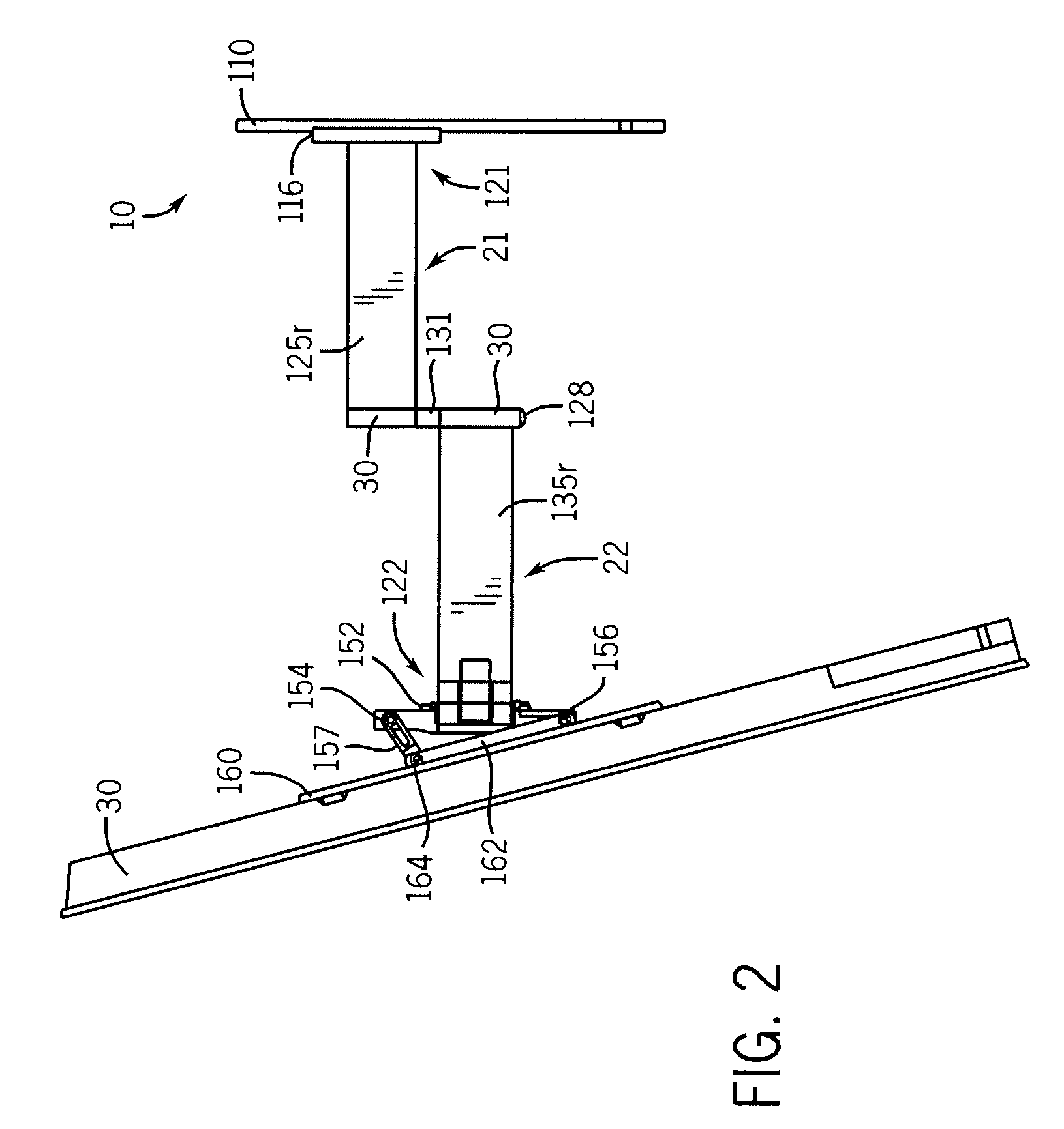
[0009]Various embodiments of the present invention provide a moveable mounting system for use with a variety of devices, particularly display devices such as flat panel displays. One or more articulating arm may be used in the various configurations of the present invention to provide translational and rotational adjustment of the attached display device in relation to a mounting surface. The display device may be adjustably orientated in relation to the mounting surface, from a retracted position proximate the surface to a fully extended position away from the wall, as well as any intermediate position therebetween. The moveable mounting system is configured to have a low profile such that the rear of the display device may be positioned in close proximity to the mounting surface when the adjustably mounting system is fully retracted, further enhancing the aesthetics of the flat panel display. The articulating arms also permit adjustable rotation of the display device up to about 90 degrees in a clockwise and counterclockwise direction. Thus, when the moveable mounting system is attached to a substantially vertical surface such as a wall, the attached display can be rotated about a substantially vertical first axis up to about 180 degrees. Furthermore, a tilting assembly mechanism can provide adjustment of the attached device with respect to the orientation and the viewing angle about a second axis of rotation substantially normal to the first axis of rotation.

Problems solved by technology

Because conventional “tube” televisions have a relatively large depth, the display options for such devices are quite limited.
Such stands or entertainment centers can take up significant floor space, which is often undesirable.
However these systems usually require professional installation and, once the television is secured to the mount, it is often difficult to access and adjust due to its height.
Although the introduction of flat panel televisions on a wide scale has presented new opportunities to both residential and commercial customers, it has also presented new challenges.
In particular, flat panel televisions, while usually having significantly smaller depth or profile than conventional “tube” televisions, tend to be quite heavy.
Particularly for flat panel televisions with large screens, this weight can become prohibitively great.
Furthermore, with such weights involved and the high cost of such devices, it is important that the device be mounted correctly on the first attempt: if the device is not correctly mounted on the first try, there is a high risk of damaging the device and causing injury to those installing it.

Method used


Image

  • Multiple arm articulating mounting system
  • Multiple arm articulating mounting system
  • Multiple arm articulating mounting system

Examples


Embodiment Construction

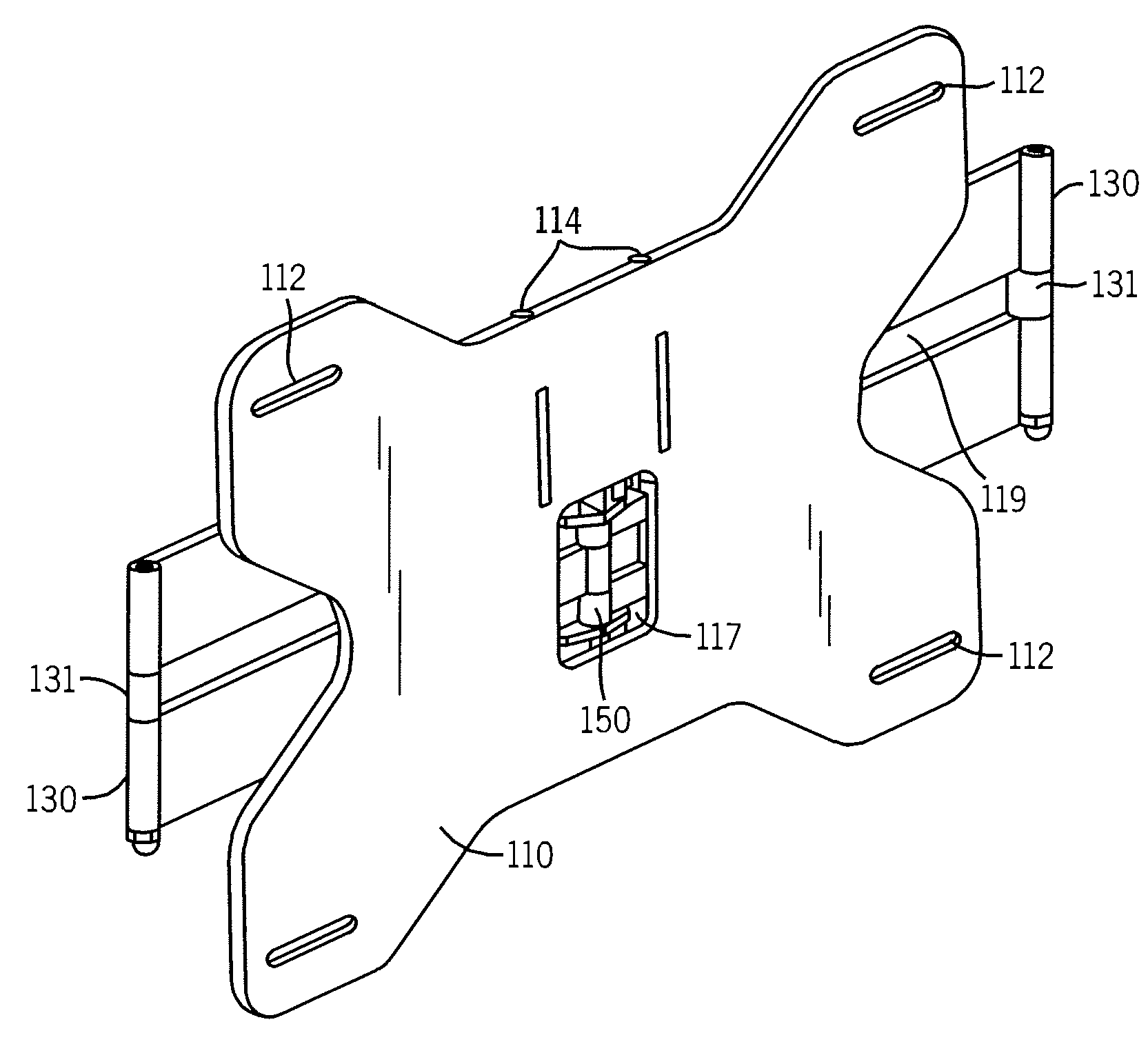
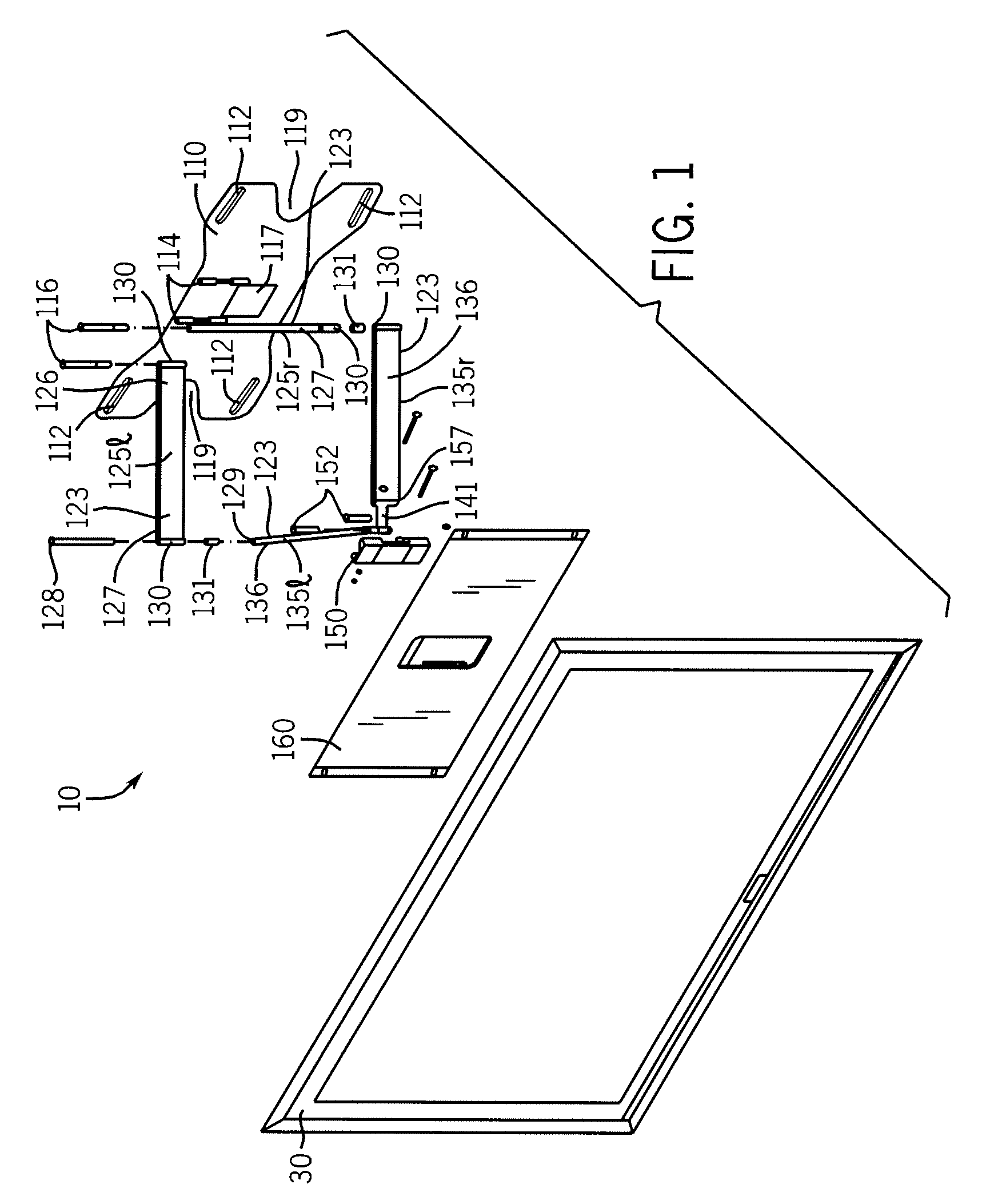
[0021]FIGS. 1-9 show a moveable mounting system 10 constructed in accordance with an embodiment of the present invention. The moveable mounting system 10 comprises a surface plate 110, an arm assembly 120 that includes a surface end 121 operatively connected to the surface plate 110 and a device end 122 operatively connected to a device bracket 150, and a device adapter 160 operatively connected to the device bracket 150. The arm assembly 120 comprises one or more arms rotatably attached to one another and may include, as shown, a first arm assembly 21 and a second arm assembly 22. As discussed in detail below, the above described features may be particularly configured to provide a low profile moveable mounting system where the mounted display may be orientated in close proximity to the mounting surface when the moveable mounting system is fully retracted.

[0022]In the embodiment depicted in FIGS. 1-9, the surface plate 110 comprises a relatively thin plate that can be affixed to a ...


PUM


Abstract

A low profile moveable mounting system for mounting a device to a surface. According to various embodiments, a first pair of rotating arms is rotatably connected to a surface plate attachable to a surface, and a second pair of arms are rotatably connected to the first pair of arms and to a device bracket. The moveable mounting system is selectively moveable between an extended orientation, where the device bracket is horizontally displaced from the surface and a retracted orientation, where the device bracket is positionable within close proximity of the surface. The moveable mounting system may be particularly adapted for mounting a flat panel display device.

Description

CROSS-REFERENCE TO RELATED PATENT APPLICATIONS[0001]This application claims priority from U.S. Provisional Application No. 61 / 142,555 filed Jan. 5, 2009 and the contents of which are incorporated herein by reference in their entirety.FIELD OF THE INVENTION[0002]The present invention relates generally to mounting systems. More particularly, the present invention relates to moveable mounting systems with articulating arms for use with flat panel televisions, where the position of the television can be adjusted after installation.BACKGROUND OF THE INVENTION[0003]This section is intended to provide a background or context to the invention that is recited in the claims. The description herein may include concepts that could be pursued, but are not necessarily ones that have been previously conceived or pursued. Therefore, unless otherwise indicated herein, what is described in this section is not prior art to the description and claims in this application and is not admitted to be prior ...

Claims


Application Information

Patent Timeline
IPC IPC(8): H05K7/00F16M13/02
CPCF16M11/10F16M11/2014F16M11/38F16M13/02
Inventor MONACO, GARRY
Owner PEERLESS INDS
Learn More