Low-Voltage Connection with Safety Circuit and Method for Determining Proper Connection Polarity

a safety circuit and low-voltage connection technology, applied in the field of batteries, can solve the problems of increasing component cost, achieve the effects of improving connection safety and functionality, reducing or preventing inductive voltage spikes, and improving safety

Inactive Publication Date: 2010-07-08
ENERGY SAFE TECH
View PDF10 Cites 25 Cited by
  • Summary
  • Abstract
  • Description
  • Claims
  • Application Information

AI Technical Summary

Benefits of technology

[0007]Implementation of the invention provides a safety circuit for use in low-voltage systems that improves safety of and provides additional features to low-voltage connections. When incorporated into a battery, the circuit leaves the battery disconnected from the low-voltage system until it determines that it is safe to make a connection. When the safety circuit determines that no unsafe conditions exist and that it is safe to connect the battery, the safety circuit may connect the battery by way of a “soft start” that provides a connection over a period of time that reduces or prevents inductive voltage spikes on the low-voltage system. A method is used for detection of proper polarity of the connections between the battery and the low-voltage system. When incorporated into a jumper cable, the safety circuit provides communication abilities, can provide test abilities, and improves connection safety and functionality, such as allowing transfer of power between low-voltage systems having different voltages.

Problems solved by technology

In some instances, the safety circuit refuses to make a connection to the low-voltage system while an unsafe condition exists.
While such implementations provide no additional safety benefit over implementations not providing automatic polarity reversal as the connection is not completed when a reversed polarity is detected, the added convenience of not requiring manual polarity correction may justify the added component cost in some instances.

Method used


Image

  • Low-Voltage Connection with Safety Circuit and Method for Determining Proper Connection Polarity
  • Low-Voltage Connection with Safety Circuit and Method for Determining Proper Connection Polarity
  • Low-Voltage Connection with Safety Circuit and Method for Determining Proper Connection Polarity

Examples


Embodiment Construction

[0024]A description of embodiments of the present invention will now be given with reference to the Figures. It is expected that the present invention may take many other forms and shapes, hence the following disclosure is intended to be illustrative and not limiting, and the scope of the invention should be determined by reference to the appended claims.

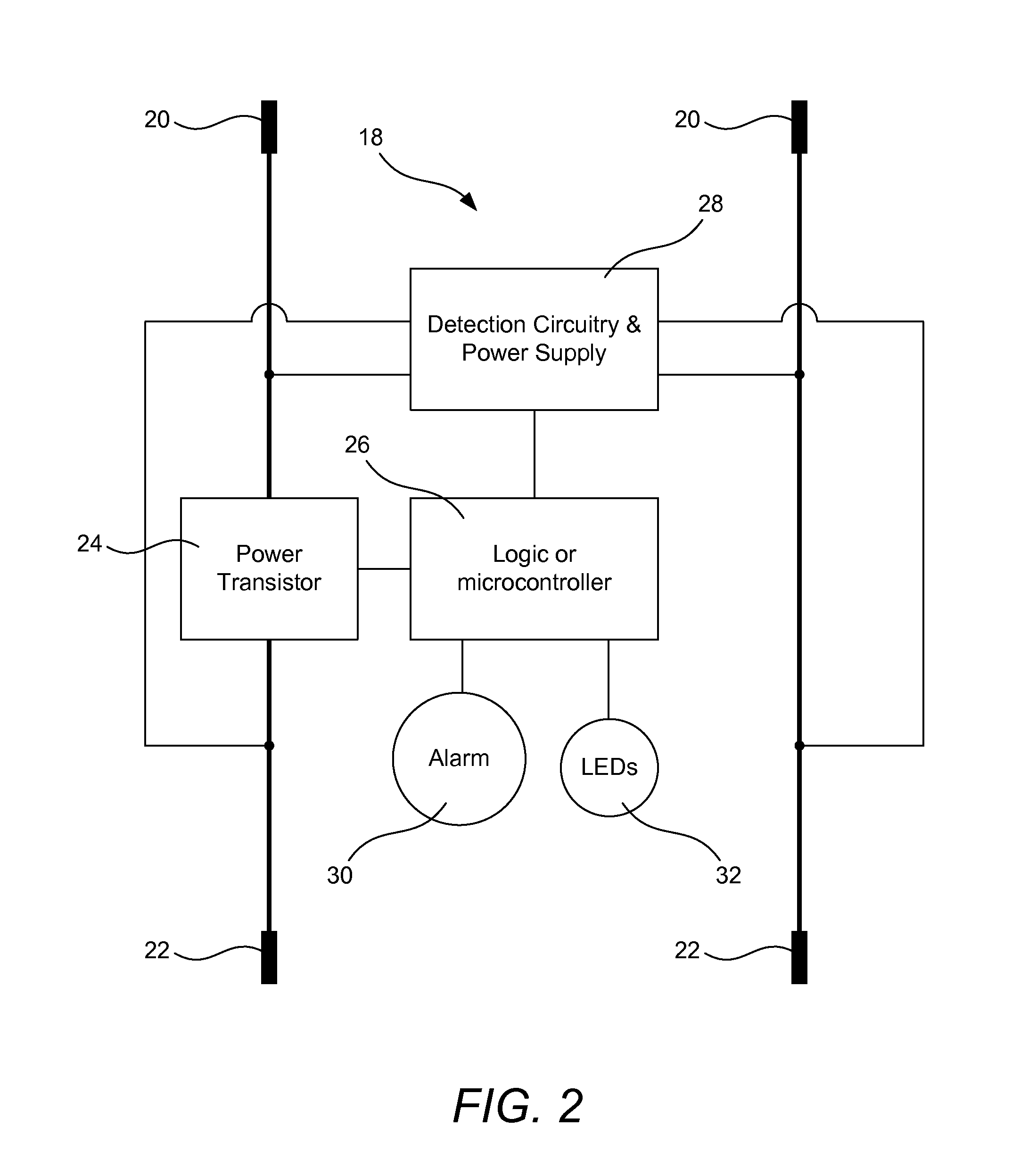
[0025]Embodiments of the invention provide a safety circuit for use in low-voltage systems that improves safety of and provides additional features to low-voltage connections. When incorporated into a battery, the circuit leaves the battery disconnected from the low-voltage system until it determines that it is safe to make a connection. When the safety circuit determines that no unsafe conditions exist and that it is safe to connect the battery, the safety circuit may connect the battery by way of a “soft start” that provides a connection over a period of time that reduces or prevents inductive voltage spikes on the low-voltage sys...


PUM

PropertyMeasurementUnit
voltageaaaaaaaaaa
timeaaaaaaaaaa
voltageaaaaaaaaaa

Abstract

A safety circuit for use in low-voltage systems improves safety of and additional features to low-voltage connections. When incorporated into a battery, the circuit leaves the battery disconnected from the low-voltage system until it determines that it is safe to make a connection. When the safety circuit determines that no unsafe conditions exist and that it is safe to connect the battery, the safety circuit may connect the battery by way of a “soft start” that provides a connection over a period of time that reduces or prevents inductive voltage spikes on the low-voltage system. A method is used for detection of proper polarity of the connections between the battery and the low-voltage system. When incorporated into a jumper cable, the safety circuit provides communication abilities, can provide test abilities, and improves connection safety and functionality, such as allowing transfer of power between low-voltage systems having different voltages.

Description

CROSS-REFERENCE TO RELATED APPLICATIONS[0001]This application is a continuation-in-part of prior application Ser. No. 12 / 559,357, filed Sep. 14, 2009, which claims the benefit of U.S. Provisional Application No. 61 / 175,696, filed May 5, 2009, and U.S. Provisional Application No. 61 / 118,511, filed Nov. 28, 2008, which applications are incorporated herein by reference in their entireties for all purposes.BACKGROUND OF THE INVENTION[0002]1. Field of the Invention[0003]The present invention relates to batteries and, more particularly, to batteries providing certain safety features.[0004]2. Background and Related Art[0005]Cables such as jumper cables are commonly used to connect two low-voltage (e.g. battery-powered) systems temporarily. However, the use of such cables can result in personal injury and equipment damage. For example, one instance where equipment damage or personal injury occurs is in the case of jump starting a car with a “dead” (i.e. partially- or totally-discharged) bat...

Claims


Application Information

Patent Timeline
Patent Type & Authority Applications(United States)
IPC IPC(8): H02H7/18H02H9/02H02H3/04H01M2/00
CPCH01M10/42H01M10/4257H02J2001/006H01M2200/00H02J7/0034H01M10/488H02J1/122H02J7/0029Y02E60/10H02J7/00304H02J7/00309
Inventor BAXTER, MICHAELWALKER, MARK
Owner ENERGY SAFE TECH
Why Eureka
Try Eureka