Microwave heating apparatus

Inactive Publication Date: 2010-07-15
PANASONIC CORP
View PDF5 Cites 105 Cited by
  • Summary
  • Abstract
  • Description
  • Claims
  • Application Information

AI Technical Summary

Benefits of technology

[0048]According to microwave heating apparatus in the present invention, its convenience is enhanced with the plurality of doors, and the convenience is further enhanced by arranging the plurality of microwave supply means for radiating

Problems solved by technology

When an electromagnetic field distribution of the microwave in the heating

Method used


Image

  • Microwave heating apparatus
  • Microwave heating apparatus
  • Microwave heating apparatus

Examples


first embodiment

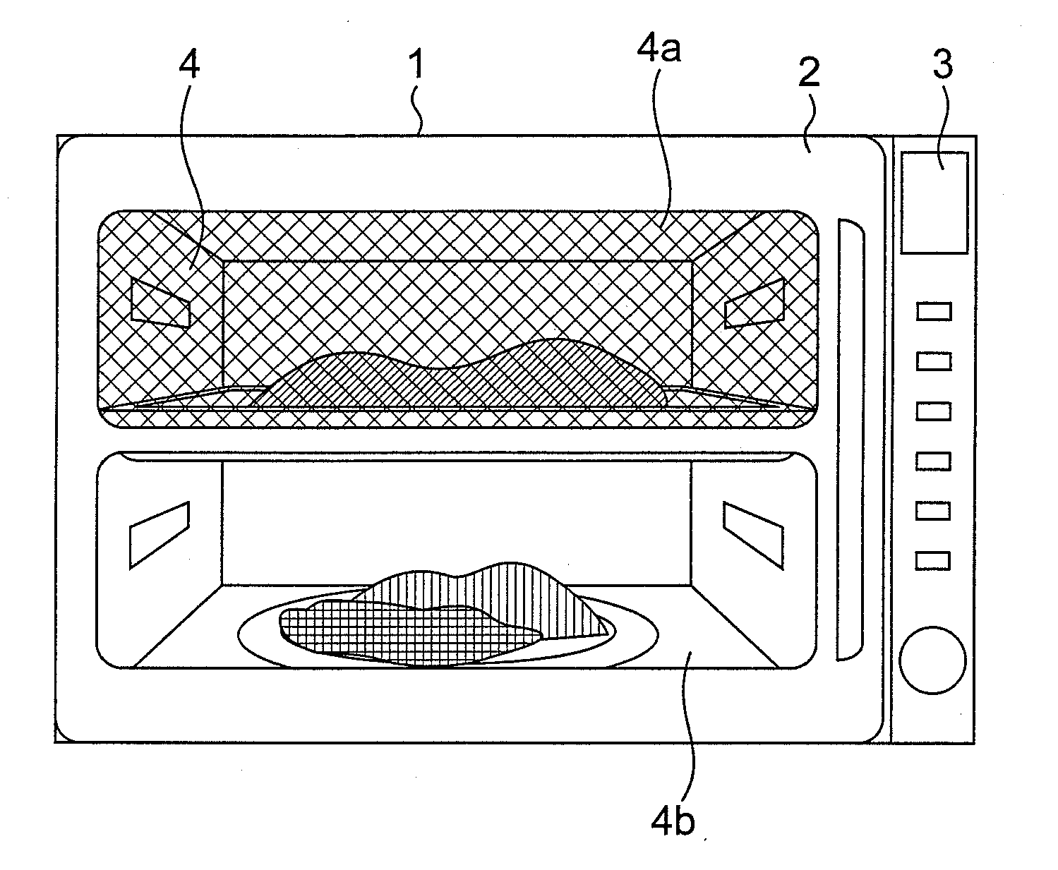
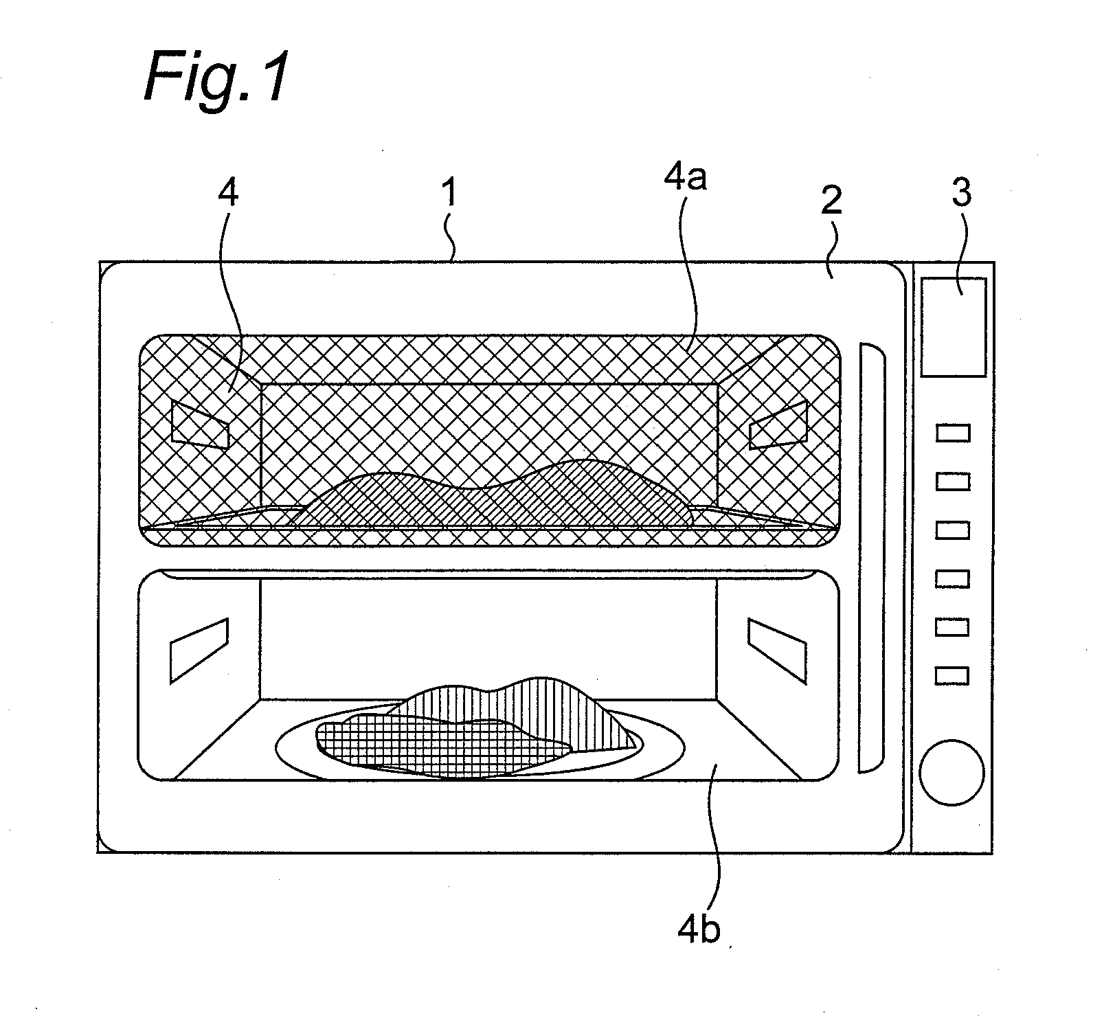
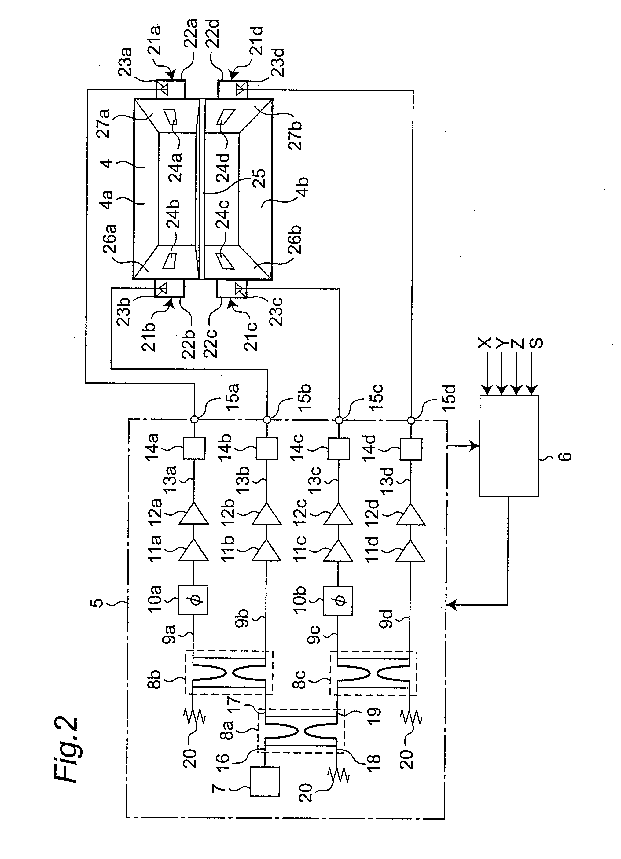
[0080]FIG. 1 is a front view showing an outline of a microwave heating apparatus according to a first embodiment of the present invention. FIG. 2 is a block diagram showing a constitution of a microwave supply system in the microwave heating apparatus according to the first embodiment.

[0081]As shown in FIG. 1, a microwave oven 1 serving as the microwave heating apparatus according to the first embodiment is provided with a door 2 having upper and lower windows at the front, and a heating chamber 4 for an object to be heated is divided into two parts such as an upper heating chamber 4a and a lower heating chamber 4b. According to the microwave heating apparatus in the first embodiment, a user sets heating conditions of the upper heating chamber 4a and / or the lower heating chamber 4b on an operation display panel 3 provided at the front, and the heating condition and a processed state of the object to be heated can be displayed thereon.

[0082]According to the constitution of the microw...

second embodiment

[0115]A microwave heating apparatus according to a second embodiment of the present invention will be described with reference to accompanying FIG. 13. FIG. 13 is a block diagram showing a constitution of a microwave supply system of the microwave heating apparatus according to the second embodiment.

[0116]The microwave heating apparatus according to the second embodiment differs from the microwave heating apparatus according to the first embodiment by arrangement of feeding parts in a heating chamber. The same reference symbol is assigned to the one having the same function and the constitution as that of the first embodiment, and the description in the first embodiment is applied to it. Description will be made of a different point between the microwave heating apparatus in the first embodiment and the microwave heating apparatus in the second embodiment hereinafter.

[0117]As shown in FIG. 13, a feeding part 21a and a feeding part 21b are arranged at crossed positions in an upper he...

third embodiment

[0122]A microwave heating apparatus according to a third embodiment of the present invention will be described with reference to accompanying FIGS. 14 to 17. FIG. 14 is a front view showing an appearance of the microwave heating apparatus in the third embodiment. FIG. 15 is a view showing only a heating chamber in the microwave heating apparatus according to the third embodiment, taken from the front. FIGS. 16 and 17 are views showing a partition plate serving as a partition unit used in the microwave heating apparatus according to the third embodiment.

[0123]As shown in FIGS. 14 and 15, according to the microwave heating apparatus in the third embodiment, similar to the microwave heating apparatus in the first embodiment, a heating chamber 4 is divided into an upper heating chamber 4a and a lower heating chamber 4b. The microwave heating apparatus in the third embodiment includes an upper door 30a and a lower door 30b on its front, through which objects of heating is put in and take...


PUM


Abstract

A microwave heating apparatus includes a microwave generation part (5) having a plurality of output parts, a heating chamber (4) to contain an object to be heated, a plurality of feeding parts (21a, 21b, 21c, 21d) supplying outputs of the plurality of output parts to the heating chamber, and a control part (6) controlling microwave radiation from the plurality of feeding parts to control an electromagnetic wave distribution in the heating chamber, in which a microwave is concentrated on the object to be heated put in the heating chamber.

Description

TECHNICAL FIELD[0001]The present invention relates to a microwave heating apparatus for heating an object to be heated, that is a heating target, by irradiating with a microwave.BACKGROUND ART[0002]A representative apparatus of the microwave heating apparatus heating a target material with a microwave includes a microwave oven. According to the microwave oven, a microwave generated by a microwave generator is radiated into a metal heating chamber, and an object to be heated is heated with the radiated microwave.[0003]Magnetron is used in a microwave generator in a conventional microwave oven. A microwave generated by magnetron is supplied into a heating chamber through a waveguide.[0004]When an electromagnetic field distribution of the microwave in the heating chamber is not uniform, the object to be heated cannot be heated uniformly. Thus, a microwave oven in which the electromagnetic field distribution of the microwave in the heating chamber is uniform is proposed. For example, Ja...

Claims


Application Information

Patent Timeline
IPC IPC(8): H05B6/70
CPCH05B6/705H05B6/686Y02B40/143Y02B40/146H05B2206/044Y02B40/00H05B6/64H05B6/68F24C7/02
Inventor MIHARA, MAKOTONOBUE, TOMOTAKAYASUI, KENJIOOMORI, YOSHIHARU
Owner PANASONIC CORP
Why Eureka
Try Eureka