Barrier

a technology of barriers and fence posts, which is applied can solve the problems of not always performing well in the field of barriers, and achieve the effect of reducing injuries

Inactive Publication Date: 2010-07-15
MAWBY DANIEL
View PDF18 Cites 3 Cited by
  • Summary
  • Abstract
  • Description
  • Claims
  • Application Information

AI Technical Summary

Benefits of technology

[0008]It is further desired that barrier fence 1 respond in a predictable and safe manner to impacts directly on uprights 3, for example by unseated riders. Specifically, uprights 3 should again break way at or near their lower ends, and thereafter behave in a safe and predictable manner. To minimize injuries, such breaking away needs to occur at impact loads generally lower than the maximum lateral load 555 on rail assembly.
[0030]It is desirable, once the lower end of the upright breaks away under impact loads, that the upright move in a manner that is predictable and likely to minimize harm to animals or persons.
[0052]Where it is desired to have a re-locatable fence, the lower part may be adapted to be driven into the ground. The lower part may comprise a length of angle with a sharpened bottom edge and that is oriented so that arms of the angle face the rail when seen in horizontal cross-section. The ground anchor may include a plate that in use lies flush with the ground surface and extends rearwardly away from the lower part so as to enhance resistance to movement of the ground anchor under rearwardly directed loads applied to the rail. The said plate may comprise an extension of a plate that abuts the lower end of the upright.

Problems solved by technology

Barrier fences have been developed for horse—and other racing applications but have not always performed well in these respects.

Method used


Image

  • Barrier
  • Barrier
  • Barrier

Examples


Embodiment Construction

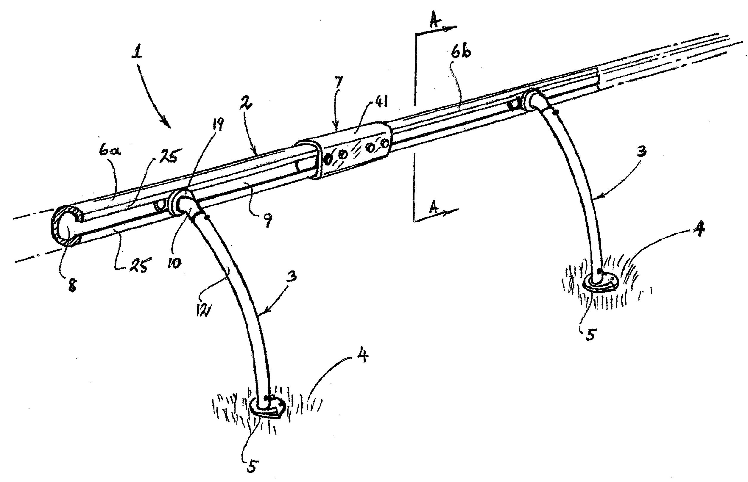
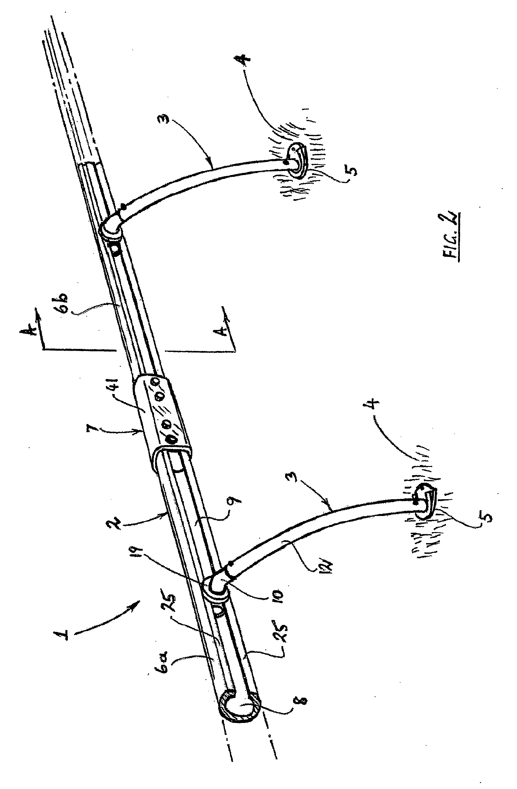
[0099]FIG. 2 shows a portion of a first barrier fence 1 according to the invention. Barrier fence 1 comprises a rail assembly 2 supported at spaced apart locations along its length by uprights 3 that are anchored to the ground 4 by anchors 5. Although only two uprights 3 are shown in FIG. 2, and a short length of the rail assembly 2, it is to be understood that barrier fence 1 can be made in any required length by providing a longer rail assembly 2 and more uprights 3 and ground anchors 5 than are shown.

[0100]In FIG. 2, barrier fence 1 is shown as seen by an observer positioned on the side of barrier fence 1 opposite that on which horses would pass, the uprights 3 being placed so as not to interfere with the horses' progress. For convenience, the side of the barrier fence 1 on which horses pass will be referred to herein as the “front” side of the barrier fence 1 and the opposite side will be described as the “rear” side of the barrier fence 1. The same convention will be used in re...


PUM

PropertyMeasurementUnit
angleaaaaaaaaaa
angleaaaaaaaaaa
angleaaaaaaaaaa

Abstract

A barrier fence for horse racing courses and the like having a rail assembly, uprights and ground anchors for the uprights' lower ends. Fence can resiliently deflect under side loads applied to the rail assembly, but in the event of an excessive value of such load, or of an impact load applied directly to an upright, that upright can break away from its ground anchor at its lower end. Multiple breakaway mechanisms can be provided. Upper ends of the uprights are secured to the rail assembly and in the event of an upright breaking away at its lower end it can rotate about a horizontal axis.

Description

TECHNICAL FIELD[0001]This invention concerns a barrier fence for use in bounding horse racing tracks and other similar applications. The barrier is readily assembled and able to absorb impacts in a safe and predictable manner.BACKGROUND ART[0002]In the sport of horse racing, elongate fences are provided to act as boundaries of the actual courses on which the horses race. It is desirable that such fences be able to be installed and relocated reasonably easily, and most importantly that they present the smallest possible hazard to horses and jockeys in the event of one or more of them falling. Barrier fences have been developed for horse—and other racing applications but have not always performed well in these respects.[0003]The present invention provides a barrier fence that is comparatively easy to install, to remove, to relocate and to repair, and that can be designed to restrict the potential for harm to horses and jockeys in the event of a fall or other accident.DISCLOSURE OF INV...

Claims


Application Information

Patent Timeline
Patent Type & Authority Applications(United States)
IPC IPC(8): A63K3/00E04H17/14B23P17/04
CPCA63K1/00Y10T29/49826E04H12/2215
Inventor MAWBY, DANIEL
Owner MAWBY DANIEL
Why Eureka
Try Eureka