Eye therapy system

Inactive Publication Date: 2010-07-22
AVEDRO
View PDF100 Cites 24 Cited by
  • Summary
  • Abstract
  • Description
  • Claims
  • Application Information

AI Technical Summary

Benefits of technology

[0011]Another example method comprises positioning a distal end of an applicator at or proximate to an eye, supplying an amount of energy to the applicator from an energy source to apply therapy to the eye, a first portion of the energy supplied to the applicator being transmitted through the distal end to the eye and a second portion of the energy supplied to the applicator being reflected from the distal end, supplying a coolant pulse to the eye, and detecting a signal corresponding to at least one of the energy supplied to the applicator and the energy reflected from the distal end, the signal further corresponding to the coolant pulse. A corresponding example system comprises an energy source, an applicator, a coolant delivery system operable to deliver coolant to cool the eye, and a dual directional coupler, one or more of the components of the system being configured to carry out one or more steps of the method.
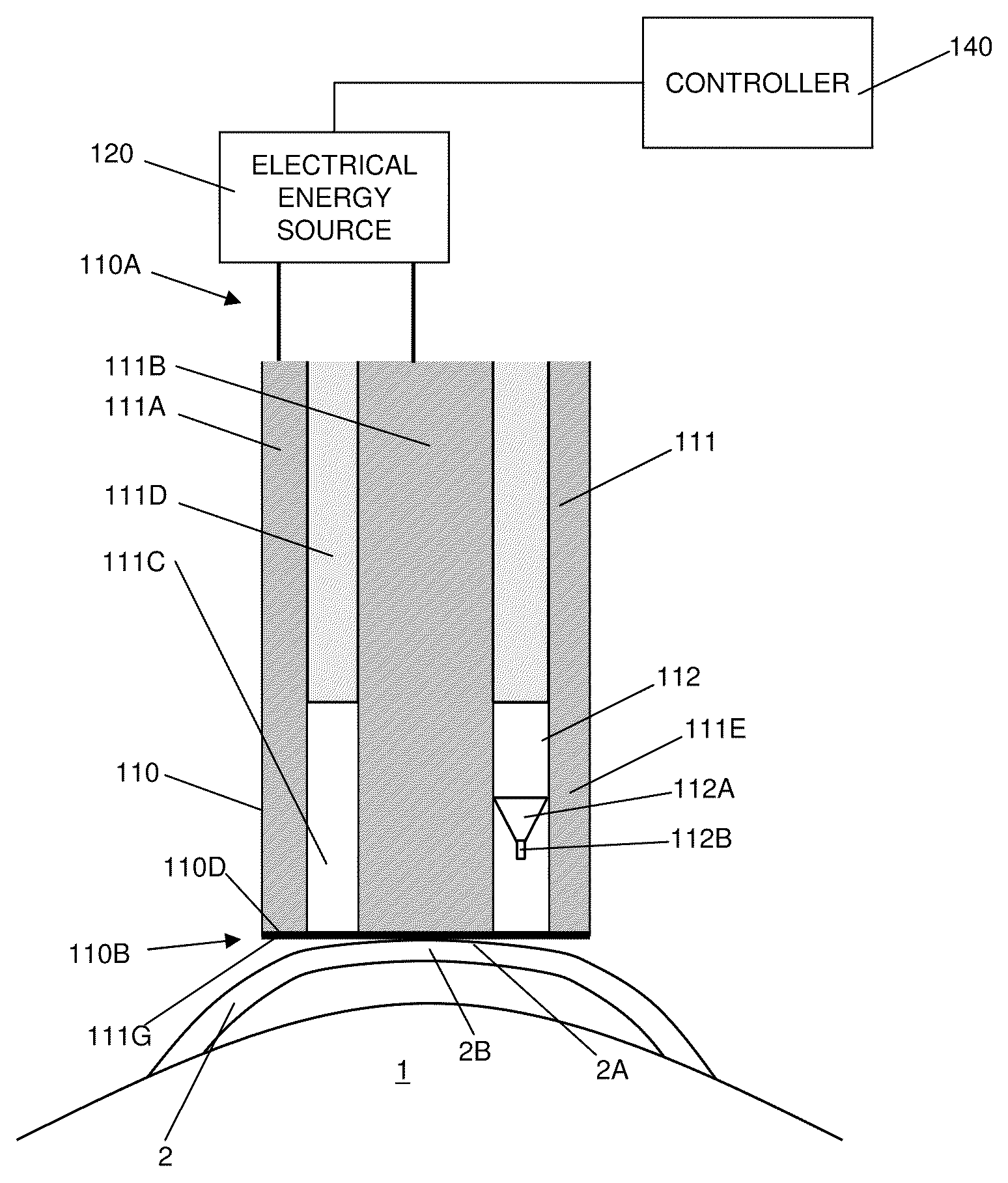
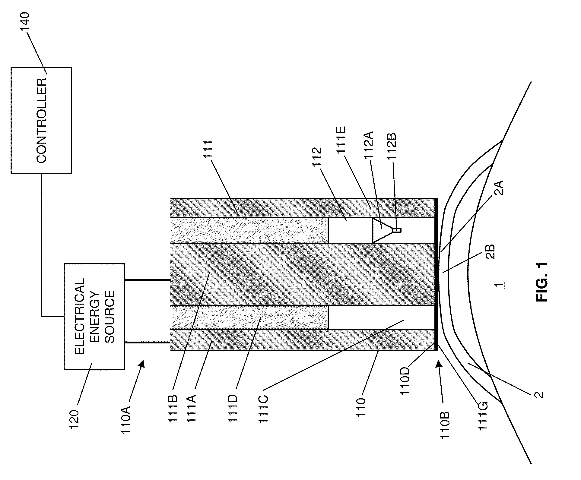
[0012]The example method may further include one or more of the following characteristics: the applicator comprises a conducting element, the conducting element being configured to conduct energy from the energy source to apply therapy to an eye, a covering configured to be removably attached to the conducting element, the covering having an interface surface positionable at the eye, at least a portion of the interface surface including one or more dielectric materials, the energy from the conducting element being deliverable to the eye through the interface surface, the covering forming an enclosure over a portion of the conducting element, and a coolant delivery system, the coolant delivery system being operable to deliver coolant within the enclosure to cool the interface surface of the covering and the eye, and the enclosure preventing the coolant from directly contacting the eye; the signal corresponds to the energy supplied to the applicator, the signal having a power, the power decreasing when coolant is delivered to the interface surface; the signal corresponds to the energy reflected from the distal end of the applicator, the signal having a power, the power increasing when coolant is delivered to the interface surface; the detecting is performed by a dual directional coupler; and the energy supplied to the applicator is a microwave energy.
[0013]Yet another method comprises supplying an amount of energy from an energy source to a distal end of an applicator to apply therapy to an eye, a first portion of the energy supplied to the applicator being transmitted through the distal end to the eye and a second portion of the energy supplied to the applicator being reflected from the distal end, detecting a forward signal corresponding to the energy supplied to the applicator, detecting a reflected signal corresponding to the reflected energy, determining an efficiency of energy transfer based on the forward signal and the reflected signal, and based on the efficiency of energy transfer, modifying at least one adjustable parameter of a tuning element corresponding to the applicator. A corresponding example system comprises an energy source, an applicator, a dual directional coupler, a tuning element, and one or more controllers, one or more of the components of the system being configured to carry out one or more steps of the method.
[0014]The method may further include one or more of the following characteristics: the determining the efficiency of energy transfer comprises measuring at least one of a magnitude change and a phase change of the forward signal and the reflected signal; the at least one adjustable parameter is an inductance; the at least one adjustable parameter is a capacitance; the at least one adjustable parameter is not modified when the efficiency of energy transfer is determined to be greater than a first threshold value; the tuning element is ele

Problems solved by technology

For example, with myopia, the cornea may be too steep or the eyeball too long, causing the refractive power of an eye to be too great and images to be focused in front of the retina.
However, such su

Method used


Image

  • Eye therapy system
  • Eye therapy system
  • Eye therapy system

Examples


Example

[0038]The embodiments described herein relate to a system and method for improving operation of an applicator that delivers heat-generating energy to an eye as a part of an eye therapy. For example, reflected power is measured to determine whether sufficient contact has been established between the applicator and the eye for accurate and precise delivery of energy to the eye. In addition, at least one of forward and reflected power is measured to monitor the application of coolant pulses that control the generation of heat in the eye when the applicator delivers energy to the eye.

[0039]Referring now to the drawings, wherein like reference characters denote similar elements throughout the several views, FIG. 1 illustrates an example system for applying heat to a cornea 2 of an eye 1 to cause reshaping of the cornea. In particular, FIG. 1 shows an applicator 110 with an electrical energy conducting element 111 that is operably connected to an electrical energy source 120, for example,...


PUM


Abstract

Systems and methods improve operation of an applicator that delivers heat-generating energy to an eye as a part of an eye therapy. For example, reflected power may be measured to determine whether sufficient contact has been established between the applicator and the eye for accurate and precise delivery of energy to the eye. In addition, at least one of forward and reflected power may be measured to monitor the application of coolant pulses that control the generation of heat in the eye when the applicator delivers energy to the eye. Further, the forward and reflected power may be measured to determine an efficiency of energy transfer or an impedance mismatch. Based on the efficiency of energy transfer or the impedance mismatch, an adjustable parameter of a tuning element may be modified.

Description

CROSS-REFERENCE TO RELATED APPLICATIONS[0001]This application claims priority to U.S. Provisional Application No. 61 / 113,395, filed Nov. 11, 2008, the contents of which are incorporated entirely herein by reference.BACKGROUND OF THE INVENTION[0002]1. Field of the Invention[0003]The invention pertains to the field of keratoplasty and, more particularly, to the application of a device configured to treat one or more eye disorders by causing corrective reshaping of an eye feature.[0004]2. Description of Related Art[0005]A variety of eye disorders, such as myopia, keratoconus, and hyperopia, involve abnormal shaping of the cornea or the eye itself. Keratoplasty reshapes the cornea to correct such disorders. For example, with myopia, the cornea may be too steep or the eyeball too long, causing the refractive power of an eye to be too great and images to be focused in front of the retina. Flattening aspects of the cornea's shape through keratoplasty decreases the refractive power of an ey...

Claims


Application Information

Patent Timeline
IPC IPC(8): A61B18/08
CPCA61B18/18A61B18/1815A61F9/0079A61B2090/065
Inventor MULLER, DAVIDPERTAUB, RADHAMEYERS, STEVENDRESHER, RUSSRYAN, THOMASSCHARF, RONALD
Owner AVEDRO
Why Eureka
Try Eureka