Apparatus and method for stabilizing adjacent bone portions

a bone and bone technology, applied in the field of stabilizing adjacent bone portions, can solve the problems of chronic and/or debilitating back pain, nerves passing near the affected area may be compressed and consequently irritated, and cannot afford stability in all dimensions

Active Publication Date: 2010-07-22
ZAVATION MEDICAL PROD LLC +1
View PDF57 Cites 118 Cited by
  • Summary
  • Abstract
  • Description
  • Claims
  • Application Information

AI Technical Summary

Problems solved by technology

While screws are generally effective for this purpose, they are limited in the sense that they do not afford stability in all dimensions required to effect the optimal or desired rigidity.
When one or more disks degenerate through accident or disease, nerves passing near the affected area may be compressed and are consequently irritated.
The result may be chronic and / or debilitating back pain.
One significant challenge to providing fusion grant stability (prior to actual bone ingrowth fusion) is preventing spinal extension during patient movement.
Distraction of the vertebral space containing the fusion graft may cause the graft to shift or move disrupting bone ingrowth fusion and causing pain.
Generally, existing spinal fusion technology has been limited or lacking in certain respects.
Among the limitations of certain of these systems is the requirement that complicated steps be performed to effect their use.
Others of these systems lack the optimal multi-dimensional stability, while others are less than desirable because they utilize components that project to externally of one or more of the bone portions between which the spacer is located.
The systems that rely upon the use of screws normally have such limitations.
Generally these systems do not effectively allow compression forces to be generated between the spacers and adjacent bone portions.
Further, while the screws stabilize the bone-spacer junction in one plane, that is normally flexion-extension, they do not control bending in plane orthogonal to the plane of the screw, that is normally side-to-side bending.
A further problem with existing systems is that parts typically are not locked and are thus prone to working loose.

Method used


Image

  • Apparatus and method for stabilizing adjacent bone portions
  • Apparatus and method for stabilizing adjacent bone portions
  • Apparatus and method for stabilizing adjacent bone portions

Examples


Embodiment Construction

[0061]Embodiments of the invention will now be described with reference to the Figures, wherein like numerals reflect like elements throughout. The terminology used in the description presented herein is not intended to be interpreted in any limited or restrictive way, simply because it is being utilized in conjunction with detailed description of certain specific embodiments of the invention. Furthermore, embodiments of the invention may include several novel features, no single one of which is solely responsible for its desirable attributes or which is essential to practicing the invention described herein.

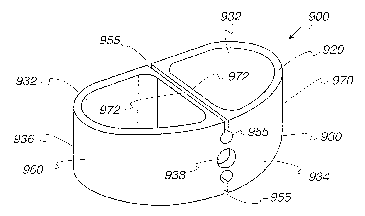
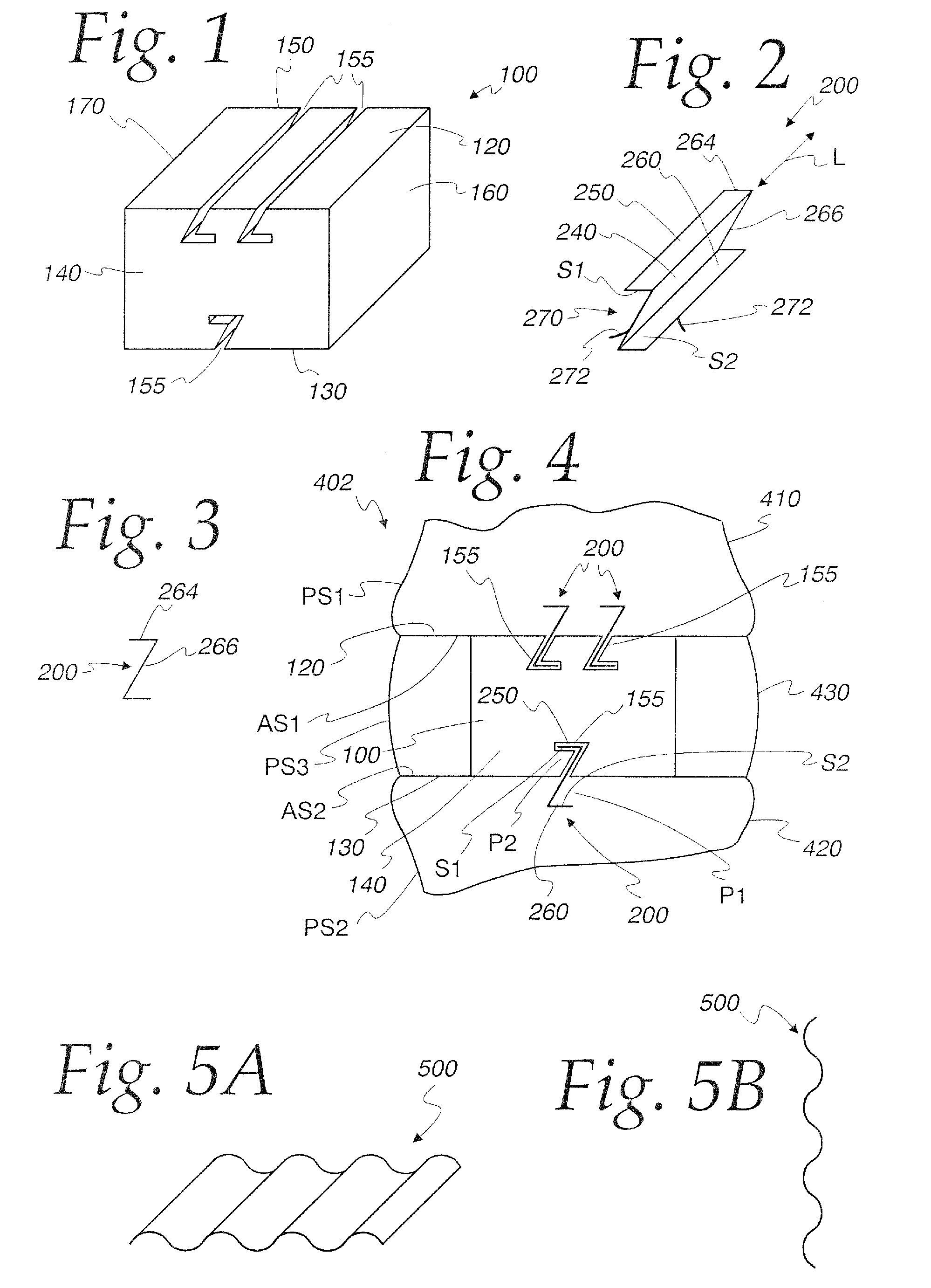
[0062]FIG. 1 illustrates schematically one embodiment of an interbody spacer 100. The spacer 100 can be used between any adjacent bone portions, such as members at a joint, in a void between such joint portions as might be developed by a fracture, through a procedure that removes bone as with a tumor, etc. While the invention is contemplated for use with virtually any adjacent b...


PUM


Abstract

An apparatus and method for stabilizing first and second adjacent bone portions. The apparatus has a spacer configured to be placed between the first and second bone portions and at least one stabilizer configured to be joined: a) to each of the first bone portion and the spacer; and b) to at least one of the first bone portion and spacer by being translated relative to the at least one of the first bone portion and spacer.

Description

BACKGROUND OF THE INVENTION[0001]1. Field of the Invention[0002]The present invention relates generally to the stabilization of adjacent bone portions, and more particularly to an apparatus for securing interbody spacers between the adjacent bone portions. The invention is also directed to a method for stabilizing the adjacent bone portions.[0003]2. Background Art[0004]Many different medical procedures are performed that require the stabilization of adjacent bone portions through the securing of an interbody spacer to the adjacent bone portions. Examples of these spacers are those known in the field as interbody cages, corpectomy cages, osteotomy wedges, joint spacers, bone void fillers, etc.[0005]As one example, spacers are used to fuse joints. Spacers are also used to repair complex fractures where bone is missing and in bone regions where there are otherwise voids, as when a tumor and adjacent bone are removed. Spacers are also used in the performance of osteotomies by placing th...

Claims


Application Information

Patent Timeline
Patent Type & Authority Applications(United States)
IPC IPC(8): A61F2/44A61B17/88
CPCA61F2/4455A61F2/4465A61F2002/2835A61F2002/30133A61F2002/30135A61F2002/30136A61F2002/30164A61F2002/30166A61F2002/30172A61F2002/30182A61F2002/30197A61F2002/3037A61F2002/3038A61F2002/30387A61F2002/30392A61F2002/30395A61F2002/30401A61F2002/30504A61F2002/30507A61F2002/30518A61F2002/30596A61F2002/30598A61F2002/30616A61F2002/30883A61F2002/30884A61F2002/30892A61F2002/4475A61F2220/0025A61F2220/0033A61F2230/0002A61F2230/0004A61F2230/0015A61F2230/0028A61F2230/0045A61F2230/0052A61F2310/00017A61F2310/00023A61F2310/00179A61F2002/30331A61F2002/305A61F2002/30594A61F2002/30593
Inventor HOCHSCHULER, STEPHENSONGER, MATTHEW N.
Owner ZAVATION MEDICAL PROD LLC
Why Eureka
Try Eureka