Flexible construct for femoral reconstruction

a flexible, femoral technology, applied in the direction of osteosynthesis devices, bone implants, bone plates, etc., can solve the problems limitations in the repair of weakened or fractured trochanters, and rigid implants that cannot allow adequate deformation to either fill the gaps created by bone degradation, and conform to existing bone surfaces, etc., to achieve the effect of promoting bone ingrowth and facilitating bone ingrowth

Active Publication Date: 2021-01-12
HOWMEDICA OSTEONICS CORP
View PDF233 Cites 3 Cited by
  • Summary
  • Abstract
  • Description
  • Claims
  • Application Information

AI Technical Summary

Problems solved by technology

Porous medical implants produced using ALM techniques, which typically require the use of biocompatible materials such as titanium, have been built with strong scaffolds, but such implants are too rigid to allow for adequate deformation to either one or both fill void spaces created by bone degradation and conform to existing bone surfaces.
As an example, repair of a weakened or fractured trochanter present limitations due to the curvature of the trochanter.

Method used


Image

  • Flexible construct for femoral reconstruction
  • Flexible construct for femoral reconstruction
  • Flexible construct for femoral reconstruction

Examples


Embodiment Construction

[0125]This invention relates generally to flexible devices for bone repair as well as to the preparation and implantation of such devices. In preferable arrangements, such devices may be prepared by additive manufacturing techniques, and in some arrangements, at least a portion of such devices may be patient-specific.

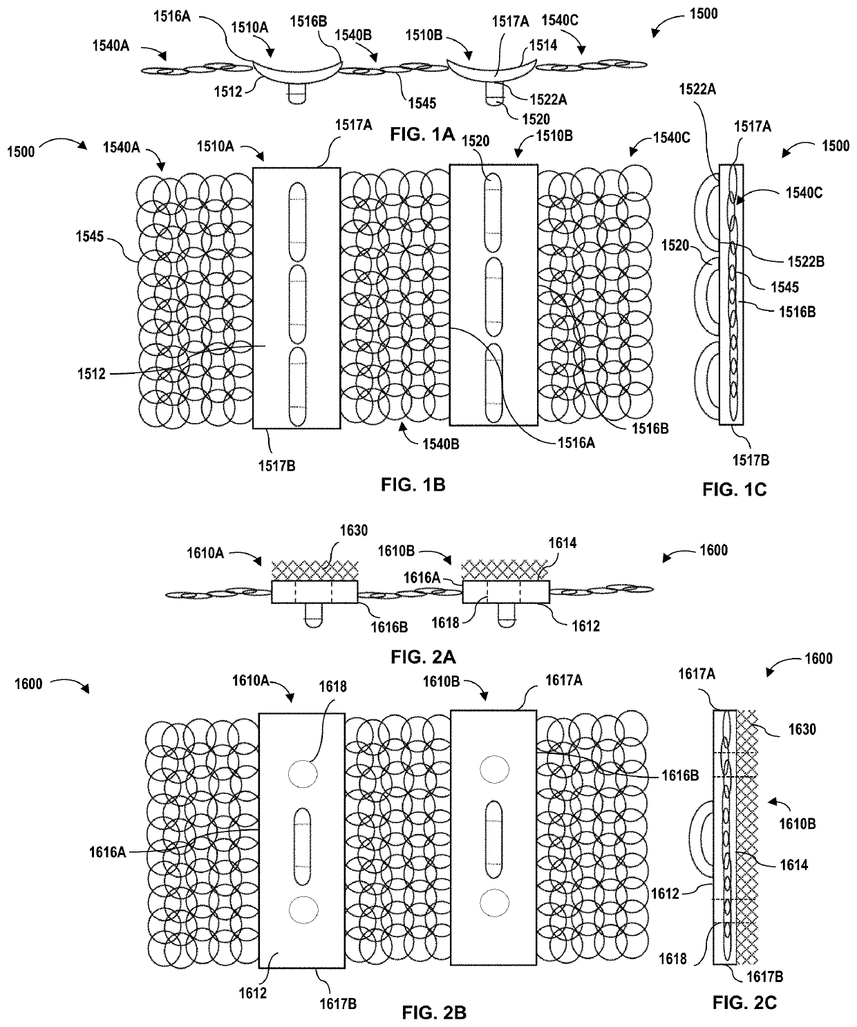
[0126]Referring now to FIGS. 1A-1C, bone repair device 1500, which may be termed a “non-biological strut graft,” includes a plurality of plates 1510A, 1510B and a plurality of flexible structures 1540A-1540C directly attached to extending from at least one of the plates. In a similar manner to that described further herein with respect to FIGS. 11A, 11B, 12A, 12B, bone repair device 1500 may be secured to a plurality of bone parts of a fractured, resected, or otherwise severed bone, e.g., the femur, to initiate osseointegration, i.e., bone ingrowth, and eventual fusion of the bone parts to repair the bone.

[0127]In this example, flexible structure 1540A is attached only ...


PUM


Abstract

A bone repair device includes a plate having a pathway and a flexible structure. The plate includes opposing top and bottom surfaces and a first side extending between the top and the bottom surfaces. The flexible structure is directly attached to and extends from the first side of the plate. In operation, the bone repair device is placed around and over a plurality of bone parts. The plate is secured to the plurality of bone parts with a cable inserted through the pathway and wrapped around the bone parts.

Description

CROSS-REFERENCE TO RELATED APPLICATION[0001]The present application claims the benefit of the filing date of U.S. Provisional Application No. 62 / 581,259 filed Nov. 3, 2017, the disclosure of which is hereby incorporated herein by reference.FIELD OF THE INVENTION[0002]The present invention relates generally to flexible devices for bone repair, and in particular to features and processes for the attachment of such devices.BACKGROUND OF THE INVENTION[0003]Examples of modern rapid manufacturing technologies include additive layer manufacturing (ALM) techniques such as electron beam melting, selective laser sintering (SLS), selective laser melting (SLM), and other three-dimensional (3-D) processes. When employing these technologies, articles are produced in layer-wise fashion from a laser-fusible powder that is dispensed one layer at a time. The powder is sintered in the case of SLS technology and melted in the case of SLM technology, by the application of laser energy that is directed i...

Claims


Application Information

Patent Timeline
Patent Type & Authority Patents(United States)
IPC IPC(8): A61B17/80A61B17/82A61F2/28
CPCA61B17/8085A61B17/8061A61B17/82A61B17/826A61F2/28
Inventor SWARTS, DALE FREDERICK
Owner HOWMEDICA OSTEONICS CORP
Why Eureka
Try Eureka