Pressure sensing device and use of the same in a connecting structure

a technology of pressure sensing device and connecting structure, which is applied in the direction of fluid pressure measurement by mechanical elements, fluid pressure measurement using elastically deformable gauges, instruments, etc., can solve the problems of air entering the system via unintentional leakage and death of patients

Active Publication Date: 2010-07-29
GAMBRO LUNDIA AB
View PDF11 Cites 13 Cited by
  • Summary
  • Abstract
  • Description
  • Claims
  • Application Information

AI Technical Summary

Benefits of technology

[0013]The pressure sensing device according to the invention provides the advantage that if an air bubble has escaped through the pressure sensing device during a dialysis treatment it can easily be forced back through the pressure sensing device and out of the extracorporeal circuit. This will be described in more detail below.

Problems solved by technology

It is also known that it may be fatal to the patient if air is introduced into his / her blood system.
Air might have come into the system via unintentional leaks.
The lines used for each dialysis treatment are disposable, since they are flown through by body fluids, such as blood, and are regarded as contaminated.

Method used


Image

  • Pressure sensing device and use of the same in a connecting structure
  • Pressure sensing device and use of the same in a connecting structure
  • Pressure sensing device and use of the same in a connecting structure

Examples


Embodiment Construction

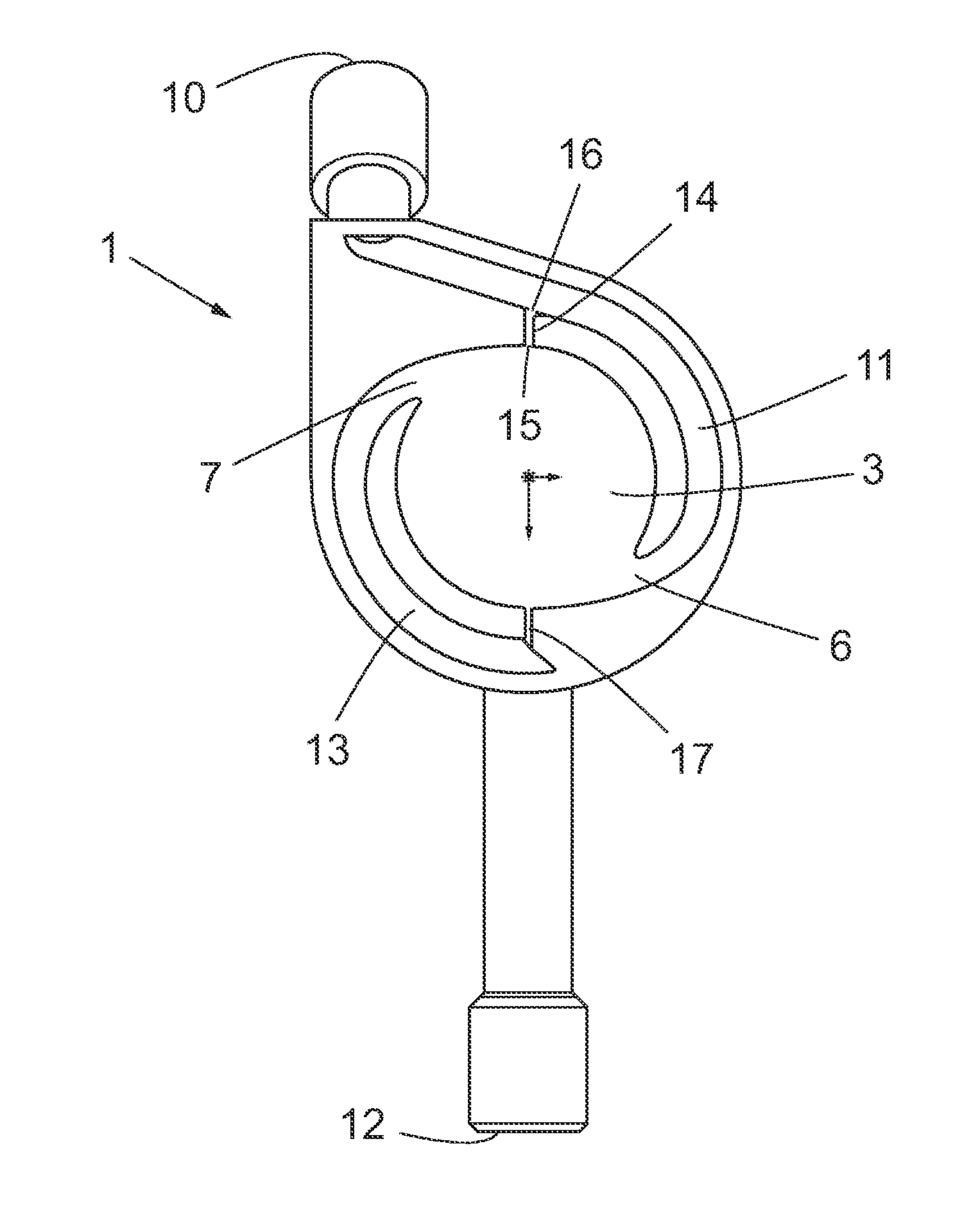
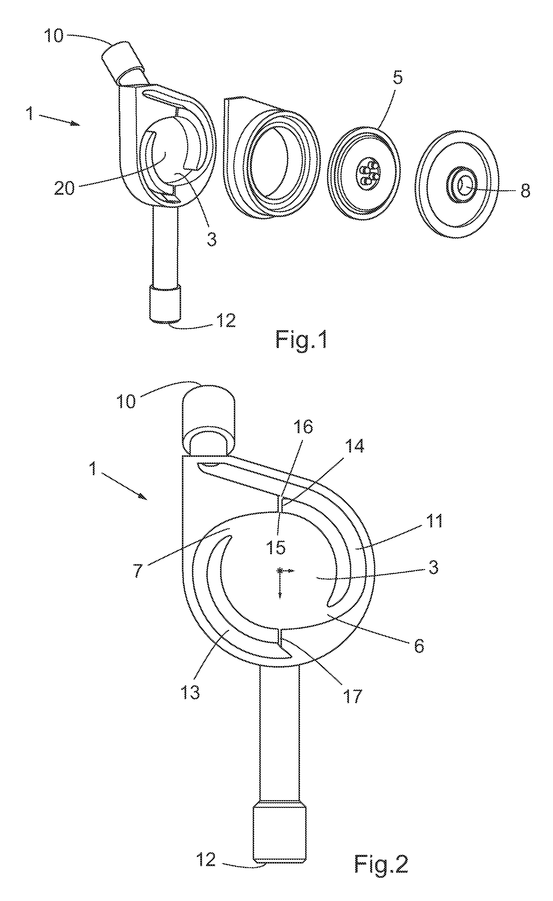
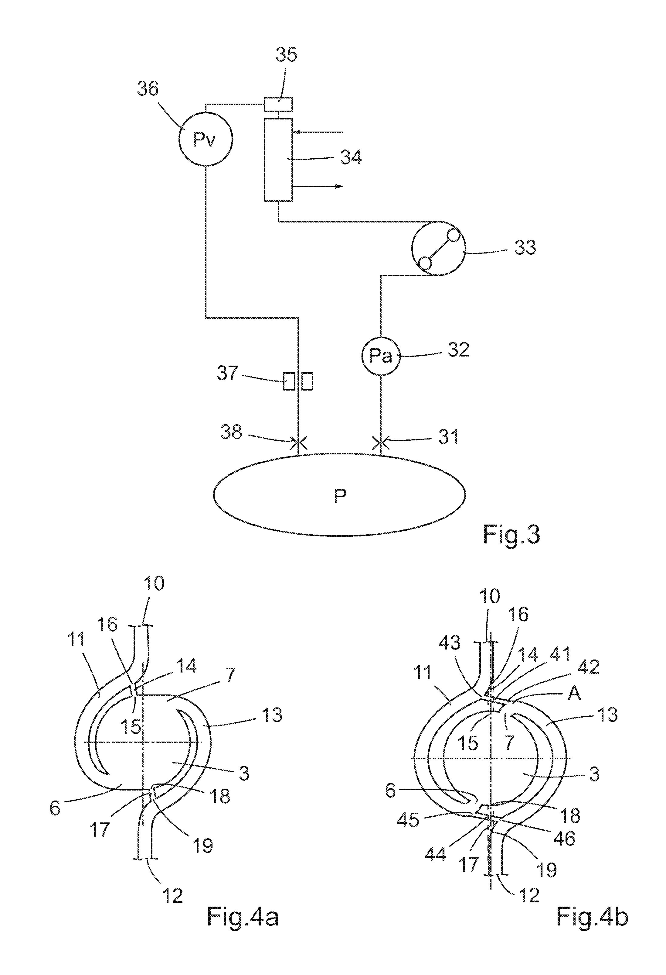
[0026]With reference to FIG. 8, the basic principle of a pressure sensing device 1 according to the prior art is shown schematically in cross section. A casing 2, which in the prior art is rigid and circular cylindrical is fluid-tightly divided into a first chamber 3 and a second chamber 4 by a circular, flexible, impermeable membrane 5. The second chamber 4 constitutes the transducer side part and has a measuring port 8 which is to be connected to an actual pressure transducer 9. The measuring port 8 is placed opposite the centre of the membrane 5. The pressure transducer 9 may be of any suitable type as is known in the art. The second chamber 4 in use contains a gas, in most cases air, and the connection to the pressure transducer 9 is gas-tight. The second chamber 4 does not come in contact with the blood or any other body fluid. The first chamber 3 is closed by the cylindrical casing 2, a side wall 20 of the cylindrical casing, and by the membrane 5 opposite the side wall 20. It...


PUM

PropertyMeasurementUnit
pressureaaaaaaaaaa
flexibleaaaaaaaaaa
flow areaaaaaaaaaaa

Abstract

A pressure sensing device adapted for having a liquid flowing there through and for sensing the pressure of said liquid. The device has a casing being fluid-tightly divided into a first and a second chamber by a flexible, impermeable wall. The first chamber has a first opening for the liquid, said opening being placed at the lower part of the chamber, and a second opening for the liquid, said opening being placed at the top of the first chamber. The second chamber has a measuring port, which is connectable to a pressure transducer for bringing the second chamber into gas-tight communication with the pressure transducer. The device has a first orifice to permit the liquid to flow into and out of the device, the orifice being placed at the upper part of the device at a higher level than the second opening. A first channel is connecting the first orifice with the first opening. A second orifice permits the liquid to flow out of and into the device and is placed at the lower part of the device at a lower level than the first opening. A second channel connects the second opening with the second orifice.

Description

TECHNICAL FIELD[0001]The present invention relates to a pressure sensing device. More particular it relates to a pressure sensing device adapted for having a liquid flowing there through and for sensing the pressure of said liquid. Said device having a casing being fluid-tightly divided into a first and a second chamber by a flexible, impermeable wall, said first chamber having a first opening for the liquid, said opening being placed at the lower part of the chamber, said first chamber having a second opening for the liquid, said opening being placed at the upper part of the chamber, said second chamber having a measuring port, which is connectable to a pressure transducer for bringing the second chamber into gas-tight communication with the pressure transducer.[0002]Use of such a pressure sensing device in a connecting structure for an extracorporeal blood treatment machine is also included.BACKGROUND OF THE INVENTION[0003]There are a number of various extracorporeal blood treatme...

Claims


Application Information

Patent Timeline
Patent Type & Authority Applications(United States)
IPC IPC(8): G01L7/00
CPCA61M1/3627A61M1/3639A61M1/3641G01L7/08
Inventor JONSSON, LENNARTJANSSON, OLOFNILSSON, EDDIE
Owner GAMBRO LUNDIA AB
Why Eureka
Try Eureka