Multi-Modal Load Control System Having Occupancy Sensing

a multi-modal, occupancy sensing technology, applied in the direction of electric variable regulation, process and machine control, instruments, etc., can solve the problem of undesirable requirement to manually actuate the keypad buttons to keep the lights on

Active Publication Date: 2010-07-29
LUTRON TECH CO LLC
View PDF16 Cites 88 Cited by
  • Summary
  • Abstract
  • Description
  • Claims
  • Application Information

AI Technical Summary

Benefits of technology

[0009]According to an embodiment of the present invention, a multi-modal load control system provides an improved procedure for controlling the amount of power delivered from an AC power source to an electrical load located in a space of a building in response to the presence or absence of an occupant in the space. The load control system comprises a sensor for detecting the presence or absence of an occupant in the space, and a load control circuit adapted to be coupled in series electrical connection between the source and the load for controlling the amount of power delivered to the load. The load control circuit is responsive to the sensor to control the amount of power delivered to the load. While the load con

Problems solved by technology

The requirement to manually actuate the buttons of the keypad to keep the l

Method used


Image

  • Multi-Modal Load Control System Having Occupancy Sensing
  • Multi-Modal Load Control System Having Occupancy Sensing
  • Multi-Modal Load Control System Having Occupancy Sensing

Examples


first embodiment

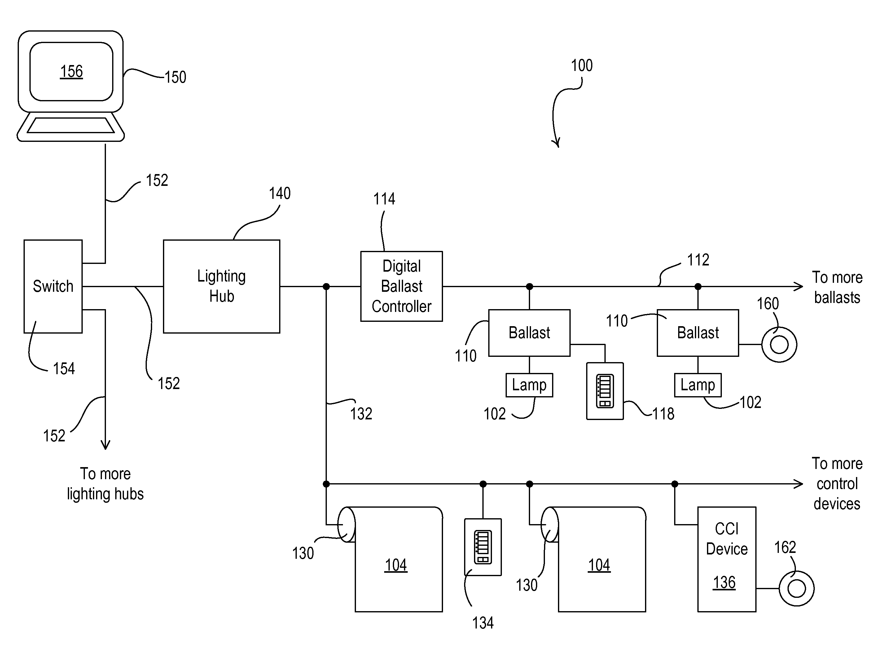
[0028]FIG. 1 is a simplified block diagram of a load control system 100, which may be installed in, for example, a commercial building, according to the present invention. The load control system 100 is operable to control the amount of power delivered from an alternating-current (AC) power source (not shown) to a plurality of electrical loads. Specifically, the load control system 100 is operable to control the level of illumination in a space of the building by controlling the intensity level of the electrical lights in the space and the daylight entering the space. As shown in FIG. 1, the load control system 100 is operable to control the amount of power delivered to (and thus the intensity of) a plurality of lighting loads, e.g., a plurality of fluorescent lamps 102. The load control system 100 is further operable to control the position of a plurality of motorized window treatments, e.g., motorized roller shades 104, to control the amount of daylight entering the space. Example...

second embodiment

[0041]FIG. 4 is a simple diagram of a radio-frequency (RF) lighting control system 400 comprising a dimmer switch 410 and two remote wireless, battery-powered sensors 420 according to the present invention. The dimmer switch 410 is adapted to be coupled in series electrical connection between an AC power source 402 and a lighting load 404 for controlling the amount of power delivered to the lighting load. The dimmer switch 410 may be adapted to be wall-mounted in a standard electrical wallbox. Alternatively, the dimmer switch 410 could be implemented as a table-top load control device. The dimmer switch 410 comprises a faceplate 412, a toggle actuator 414 (i.e., a button), and an intensity adjustment actuator 416. Actuations of the toggle actuator 414 toggle, i.e., turn off and on, the lighting load 404. Actuations of an upper portion 416A or a lower portion 416B of the intensity adjustment actuator 416 respectively increase or decrease the amount of power delivered to the lighting ...

third embodiment

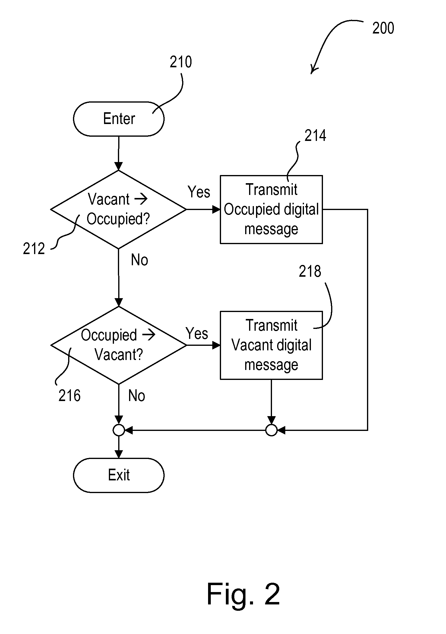
[0051]According to the present invention, the remote sensor 420 may comprise an astronomical time clock and may transmit different digital messages to the dimmer switch 410 depending upon the present time of the day. Specifically, after sunrise and before sunset (i.e., during the daylight hours), each of the remote sensors 420 transmits a digital message having an “occupied-take-action” command to the dimmer switch 410 in response to detecting an occupancy condition (i.e., the presence of an occupant) in the space. Before sunrise and after sunset (i.e., during the nighttime hours), each of the remote sensors 420 transmits a digital message having an “occupied-no-action” command to the dimmer switch 410 in response to detecting an occupancy condition in the space. During both the daylight hours and the nighttime hours, each of the remote sensors 420 transmits a digital message having a vacant command to the dimmer switch 410 in response to detecting a vacancy condition in the space.

[...


PUM


Abstract

A multi-modal load control system includes a sensor that operates as an occupancy sensor in a first mode of operation and operates as a vacancy sensor in a second mode of operation. The load control system comprises a load control circuit adapted to be coupled in series electrical connection between an AC power source and an electrical load for controlling the amount of power delivered to the load in response to sensor, which is operable to detect occupancy or vacancy conditions in a space in which the sensor is located. In the first mode of operation, the load control circuit turns the load on when the sensor detects the occupancy condition and turns the load off when the sensor detects the vacancy condition. In the second mode of operation, the load control circuit turns the load off when the sensor detects the vacancy condition and does not turn the load on when the sensor detects the occupancy condition.

Description

CROSS-REFERENCE TO RELATED APPLICATIONS[0001]This application is a non-provisional application of commonly-assigned U.S. Provisional Application Ser. No. 61 / 147,325, filed Jan. 26, 2009, entitled LIGHTING CONTROL SYSTEM HAVING AN IMPROVED AFTERHOURS MODE, the entire disclosure of which is hereby incorporated by reference.BACKGROUND OF THE INVENTION[0002]1. Field of the Invention[0003]The present invention relates to a load control system comprising a plurality of load control devices for controlling the amount of power delivered to a plurality of electrical loads from an alternating-current (AC) power source, and more particularly, to a lighting control system, which has sensors for detecting the presence and absence of an occupant and automatically changes between two modes of operation.[0004]2. Description of the Related Art[0005]Typical prior art load control systems are operable to control the amount of power delivered to an electrical load, such as, a lighting load or a motor l...

Claims


Application Information

Patent Timeline
IPC IPC(8): H05B37/02H02J3/00
CPCH02J3/14H05B37/0245H05B39/081H05B39/085H05B37/0227Y04S20/246H02J3/00H05B37/02Y02B70/3283H05B47/175H02J2310/14Y04S20/222Y02B70/3225H05B47/115H05B47/17Y02B20/40Y02B70/30
Inventor BULL, JOHN H.
Owner LUTRON TECH CO LLC
Why Eureka
Try Eureka