Magnetic waterproof switch assembly
a technology of waterproof switch and switch body, which is applied in the direction of mangetic float movement actuation, magnetic/electric field switch, electrical apparatus, etc., can solve the problems of insufficient waterproof effect of such structure, inability of metal piece controlling the switch to precisely activate the switch, and the circuit of the electronic device is broken, so as to improve competitiveness, excellent waterproof effect, and reduce costs
- Summary
- Abstract
- Description
- Claims
- Application Information
AI Technical Summary
Benefits of technology
Problems solved by technology
Method used
Image
Examples
first embodiment
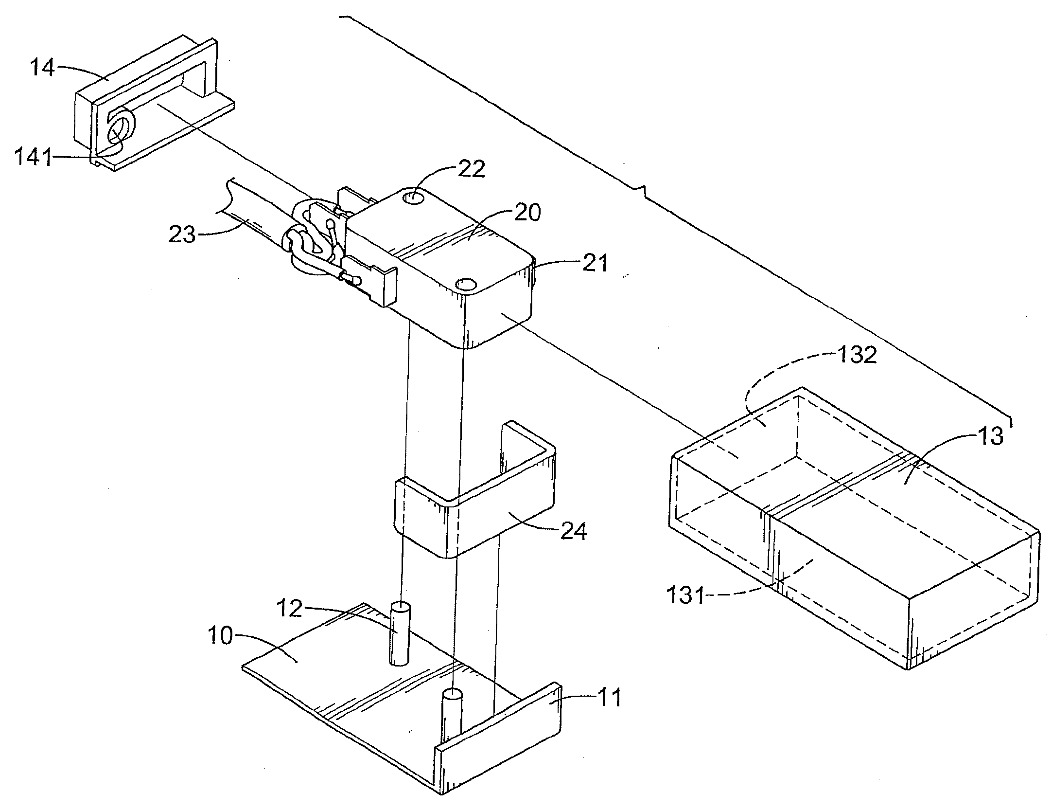
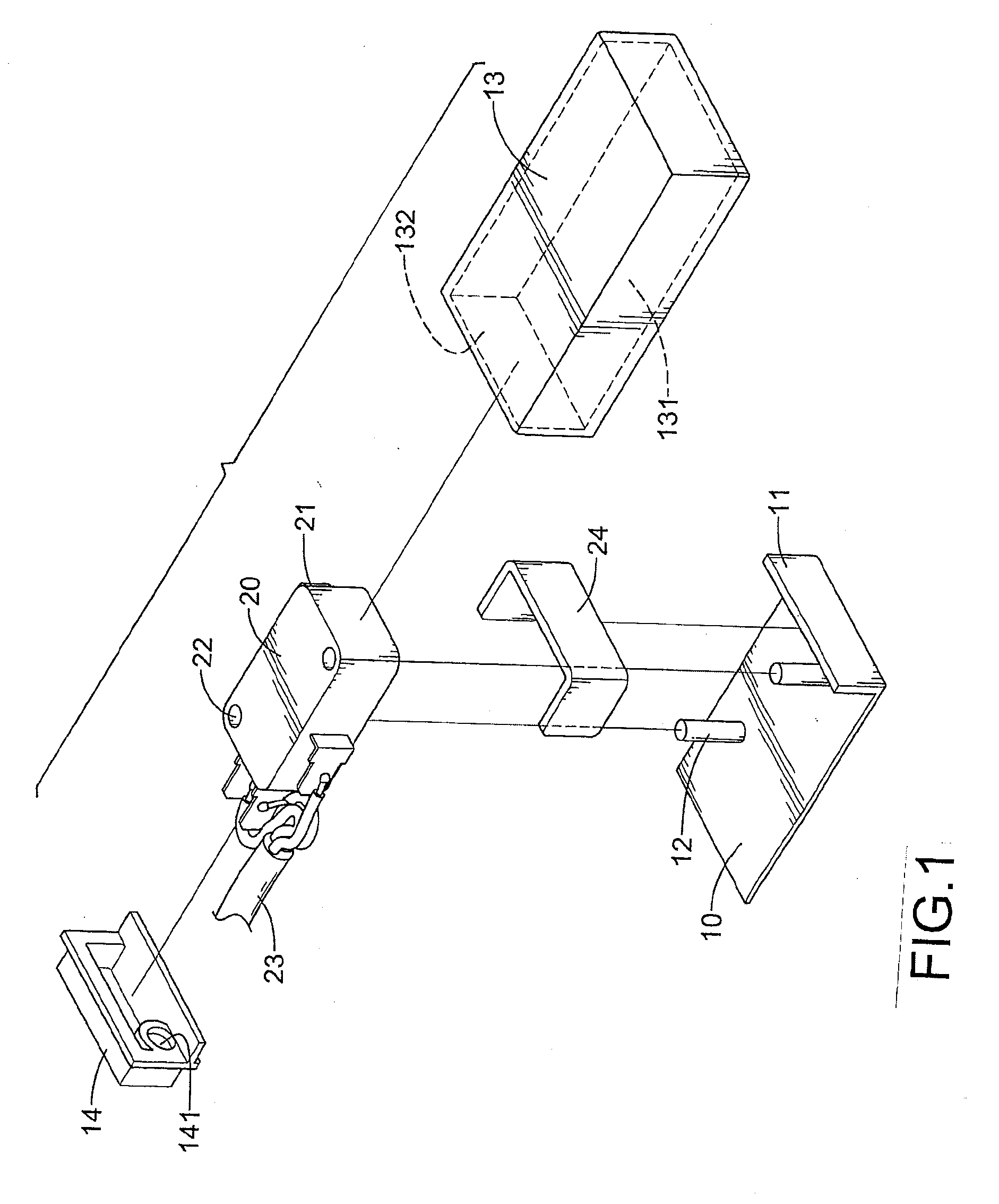
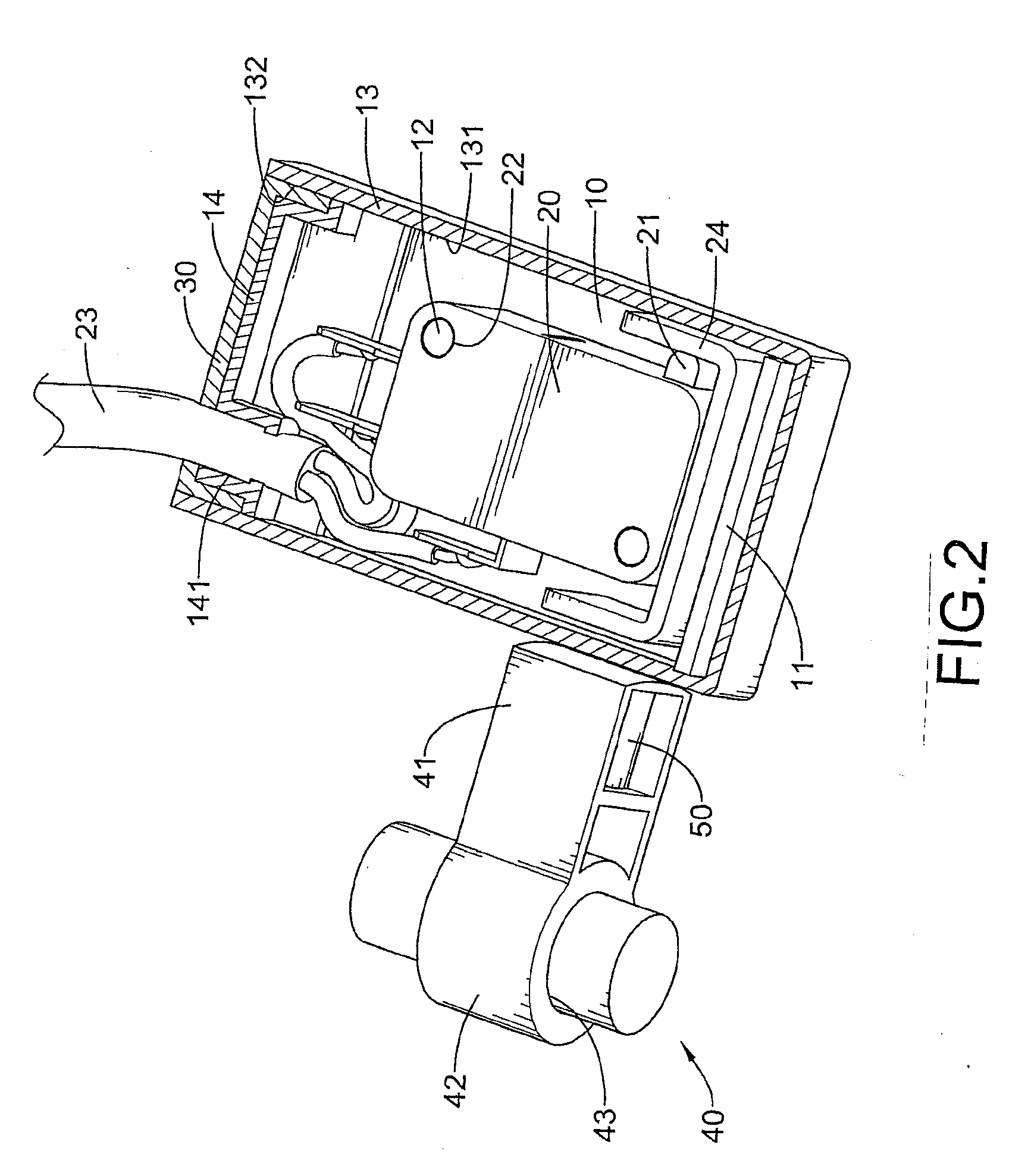
[0029]With reference to FIGS. 1 to 4, a magnetic waterproof switch assembly in accordance with the present invention comprises:
[0030]a waterproof housing 13, wherein a chamber 131 is defined therein, an entrance 132 defined in one end of the waterproof housing 13;
[0031]a bottom base 10 mounted in the waterproof housing 13, wherein a side plate 11 is formed on one side of the bottom base 10;
[0032]a switch 20 having a button 21 mounted on the bottom base 10, wherein a cable 23 is connected electrically to the button 20;
[0033]an iron sheet 24 mounted on the bottom base 10 and located adjacent to the button 21 of the switch 20;
[0034]a waterproof cover 14 covering the entrance 132 of the waterproof housing 132;
[0035]a waterproof glue 30 sealing the entrance 132 of the water casing 132; and
[0036]a magnet controlling element 40 positioned outside the waterproof housing 13 near the iron sheet 24, wherein a magnet 50 is mounted on one end thereof near the iron sheet 24.
[0037]The switch 20 ma...
second embodiment
[0042]With further reference to FIGS. 5 to 10, the magnetic waterproof switch assembly comprises:
[0043]a waterproof housing 13, wherein a chamber 131 is defined therein, an entrance 132 defined in one end of the waterproof housing 13;
[0044]a bottom base 10 mounted in the waterproof housing 13, wherein a side plate 11 is formed on one side of the bottom base 10;
[0045]a switch 20 having a button 21 mounted on the bottom base 10, wherein a cable 23 is connected electrically to the button 20;
[0046]an iron sheet 24 mounted on the bottom base 10 and located adjacent to the button 21 of the switch 20;
[0047]a waterproof cover 14 covering the entrance 132 of the waterproof housing 132;
[0048]a waterproof glue 30 sealing the entrance 132 of the water casing 132; and
[0049]a magnet controlling element 60 positioned outside the waterproof housing 13 near the iron sheet 24, wherein a magnet 70 is mounted on one end thereof near the iron sheet 24.
[0050]The difference between the first and second em...
PUM
 Abstract
Description
Claims
Application Information
 - R&D
- Intellectual Property
- Life Sciences
- Materials
- Tech Scout
- Unparalleled Data Quality
- Higher Quality Content
- 60% Fewer Hallucinations
Browse by: Latest US Patents, China's latest patents, Technical Efficacy Thesaurus, Application Domain, Technology Topic, Popular Technical Reports.
© 2025 PatSnap. All rights reserved.Legal|Privacy policy|Modern Slavery Act Transparency Statement|Sitemap|About US| Contact US: help@patsnap.com


