Brake monitoring system and method

a technology for monitoring systems and brakes, applied in brake systems, instruments, transportation and packaging, etc., can solve problems such as excessive movement, excessive movement, and additional push rod movement, and achieve the effect of limiting the speed of the vehicl

Active Publication Date: 2010-07-29
INDIAN HEAD INDUSTRIES INC
View PDF10 Cites 47 Cited by
  • Summary
  • Abstract
  • Description
  • Claims
  • Application Information

AI Technical Summary

Benefits of technology

[0015]In a first aspect of the present invention, a brake monitoring system for a vehicle having multiple axles and a plurality of brake actuators and an engine control module is provided. Each brake actuator is associated with one of the axles. The system includes a plurality of sensors, a plurality of brake lining wear sensors, a chassis communications module, and a diagnostic device. Each sensor is mounted in a respective actuator for sensing in real-time a parameter of the respective actuator and for generating a respective first signal. Each brake lining wear sensor is contained within each brake lining actuator and detects a brake wear parameter of the respective actuator and generating a respective second signal. The chassis communications module is coupled to the sensors and the brake lining wear sensors via a wire harness, receives the first and second signals and stores the first and second signals thereon. The chassis communications module detects a fault condition of one of the brakes as a function of the first and / or second signals and records the fault condition. The fault condition is one of a brake monitor warning and a brake lining warning. The chassis communications module has a plurality of warning lights. Each warning light corresponds to one of the fault conditions. The chassis communications module actuates a respective one of the warning lights in response to detecting the respective warning condition. The diagnostic device is coupled to the chassis communications control module via a datalink and receives the first and second signals and the fault conditions stored in the chassis communications control module and stores the first and second signals and the fault conditions on the diagnostic device. The fault condition may be indicative of a dragging brake condition. The chassis control module can then send a signal to the engine control module to throttle back the vehicle, or limit the speed of the vehicle and / or the RPM of the engine in response to detecting the dragging brake condition.
[0016]In a second aspect of the present invention, a method for monitoring the brakes of a vehicle having multiple axles, a plurality of brake actuators, and an engine control module is provided. Each brake actuator being is associated with one of the axles. The method includes the steps of sensing, in real-time, a parameter of each actuator, using a sensor, and for generating a respective first signal and detecting a brake wear parameter of each actuator using a brake lining wear sensor, and generating a respective second signal. Each brake lining wear sensor is contained within the respective brake lining actuator. The method further includes the steps of receiving the first and second signals at a chassis communications module via a wire harness and storing the first and second signals thereon, detecting a fault condition of one of the brakes as a function of the first and / or second signals and for recording the fault condition. The fault condition is one of a brake monitor warning and a brake lining warning. The method also includes the steps of providing, on the chassis communications module a plurality of warning lights, actuating a respective one of the warning lights in response to detecting the respective warning condition, receiving the first and second signals and the fault conditions at a diagnostic device coupled to the chassis communications control module via a datalink, and storing the first and second signals and the fault conditions thereon. The fault condition may be indicative of a dragging brake condition. The method also includes the step of sending a signal to the engine control module to throttle back the vehicle, or limit the speed of the vehicle and / or the RPM of the engine in response to detecting the dragging brake condition.

Problems solved by technology

The prior art has experienced situations wherein there has been an excessive amount of push rod movement for actuation of the brake system.
Typically, excessive movement is due to brake lining wear.
Further, as the linkages, connections, etc. between the members connecting the push rod to the brakes bend or become loose or excessively worn, additional push rod movement may be required to adequately stroke the brake.
This is, of course, an undesirable situation.
However, there are several obstacles to overcome.
First, powering and monitoring electronic indicators on each of the brake actuators on an 18-wheel vehicle is costly.
The cost in wiring alone for the vehicle exceeds the cost of all the electronic indicators and monitoring equipment combined.
Further, the hostile environment in which the brake actuators are mounted can damage the wires connecting the brake actuators to a controller.
However, the Weant system does not take into account numerous advances in sensor and system technology.

Method used


Image

  • Brake monitoring system and method
  • Brake monitoring system and method
  • Brake monitoring system and method

Examples


Embodiment Construction

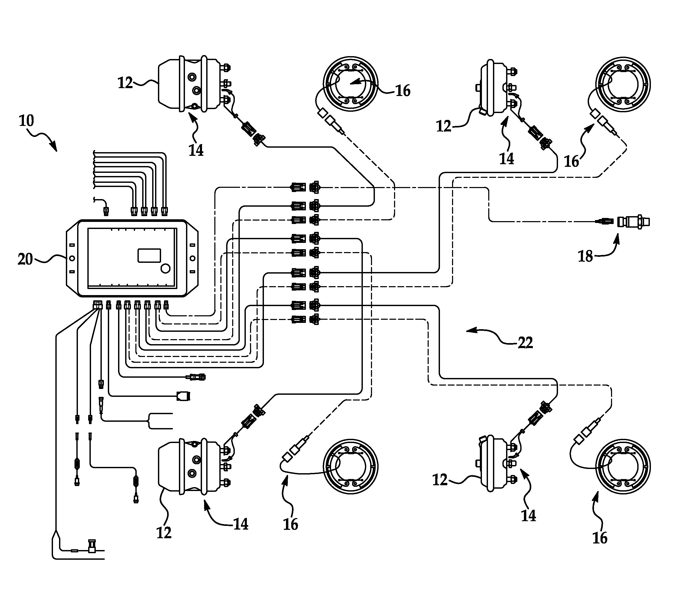
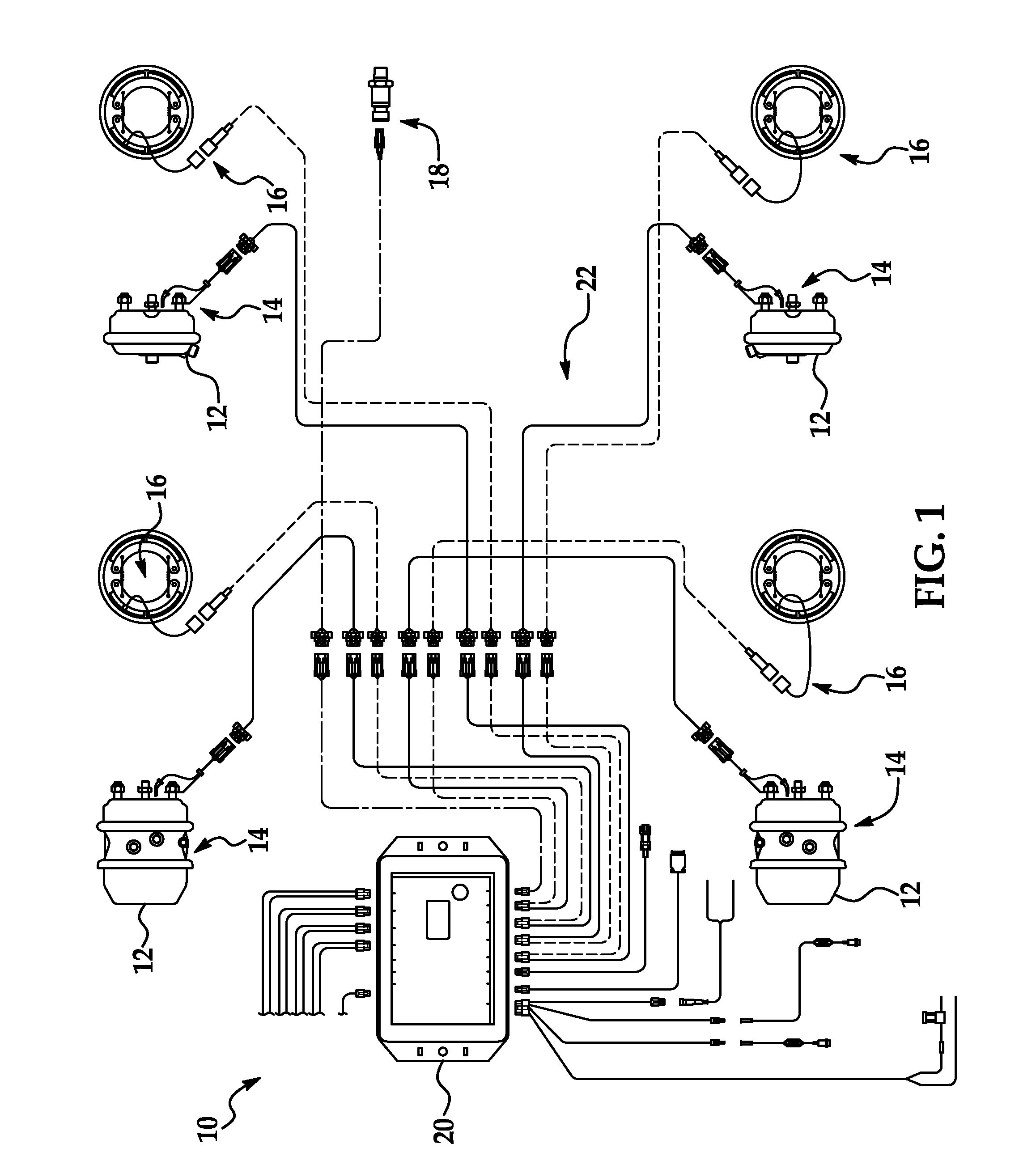
[0025]Referring to the Figures, wherein like numerals indicate like or corresponding parts throughout the several views, a brake monitoring system 10 for use with a motor vehicle (not shown) is shown. The motor vehicle includes a plurality of brake actuators 12 (in the illustrated embodiment, the motor vehicle includes 4 brake actuators 12). In the illustrated embodiment, the brake actuators 12 are drum brakes.

[0026]In general, the brake monitoring system 10 utilizes a plurality of sensors (see below) to continuously monitor the status of the brakes. One such system is disclosed in U.S. Pat. No. 6,411,206, which is hereby incorporated by reference. The brake monitoring system 10 includes an e-stroke sensor 14 mounted within each actuator 12 and a brake lining wear sensor 16. The e-stroke sensor 14 sensing a parameter of the actuator 12 which may be used in detecting over-stroke fault conditions. In one embodiment, the estroke sensor 18 provides real-time brake pressure application r...


PUM


Abstract

A brake monitoring system and method for a vehicle having multiple axles and a plurality of brake actuators and an engine control module, each brake actuator being associated with one of the axle. The system include sensors for measuring, in real-time, brake pressure and brake lining wear, and generating first and second signals. The first and second signals are received and stored in a chassis communications module. The chassis communications module detects fault condition of the brakes as a function of the first and/or second signals and for recording the fault condition, the fault condition being one of a brake monitor warning and a brake lining warning and provides an indication of status via warning lights.

Description

RELATED APPLICATIONS[0001]The present application claims priority to U.S. Provisional Application 61 / 147,029, filed Jan. 23, 2009, which is hereby incorporated by reference.FIELD OF THE INVENTION[0002]The present invention relates generally to the brake monitoring system a motor vehicle, and more particularly, to a brake monitoring system which measures, records, and can transmit actual brake pressure in real time for the purpose of detecting fault conditions and performing diagnostics, on-board and / or off-board the motor vehicle.BACKGROUND OF THE INVENTION[0003]The present invention relates to an improved brake monitoring system, particularly for use on vehicles such as a tractor and trailer combination.[0004]In the prior art, heavy duty trucks and other large vehicles are typically equipped with an air brake actuating system. The air brake actuating system applies air to a service chamber to move a diaphragm in a first direction. A push rod typically moves with the diaphragm, and ...

Claims


Application Information

Patent Timeline
Patent Type & Authority Applications(United States)
IPC IPC(8): B60Q1/00
CPCB60Q11/00B60T17/22B60W10/04Y10T477/81B60W10/188B60W30/18109B60W10/184
Inventor WALLACE, THOMAS EDWARDRINK, RICHARD J.CHANDLER, MARK DAVID
Owner INDIAN HEAD INDUSTRIES INC
Why Eureka
Try Eureka