
Vehicle control system

a control system and vehicle technology, applied in the field of vehicle control systems, can solve the problems of inability to realize the intension of the driver in sport mode properly, and the target acceleration cannot be easily reduced, so as to improve the target acceleration rate, control the vehicle speed easily, and reduce the effect of target acceleration

Active Publication Date: 2020-04-23
TOYOTA JIDOSHA KK
View PDF0 Cites 2 Cited by
  • Summary
  • Abstract
  • Description
  • Claims
  • Application Information

AI Technical Summary

Benefits of technology

The present invention relates to a vehicle control system that can be used in both a normal mode and a sport mode. The system uses different acceleration characteristics for each mode to provide the driver with better control and a more dynamic driving experience. The system allows for easy speed control and smooth acceleration in both modes. The target acceleration is reduced sensitively to changes in vehicle speed, and the driver can control the vehicle speed and acceleration easily. The vehicle control system is adaptable to different driving conditions and vehicle speeds, ensuring the driver's intent is always followed. Overall, the invention provides a more intuitive and responsive driving experience for the driver.

Problems solved by technology

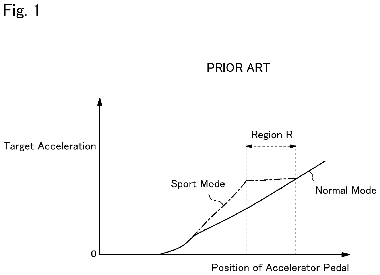
According to the teachings of US 2015 / 019091 A1, however, the driver's intension may not be realized properly in the sport-mode.
Therefore, the target acceleration will not be reduced easily even if the vehicle speed is increased.

Method used


Image

  • Vehicle control system
  • Vehicle control system
  • Vehicle control system

Examples


Embodiment Construction

)

[0025]Embodiments of the present invention will now be explained with reference to the accompanying drawings. Note that the embodiments shown below are merely examples of the present invention, and do not limit a scope of the present invention.

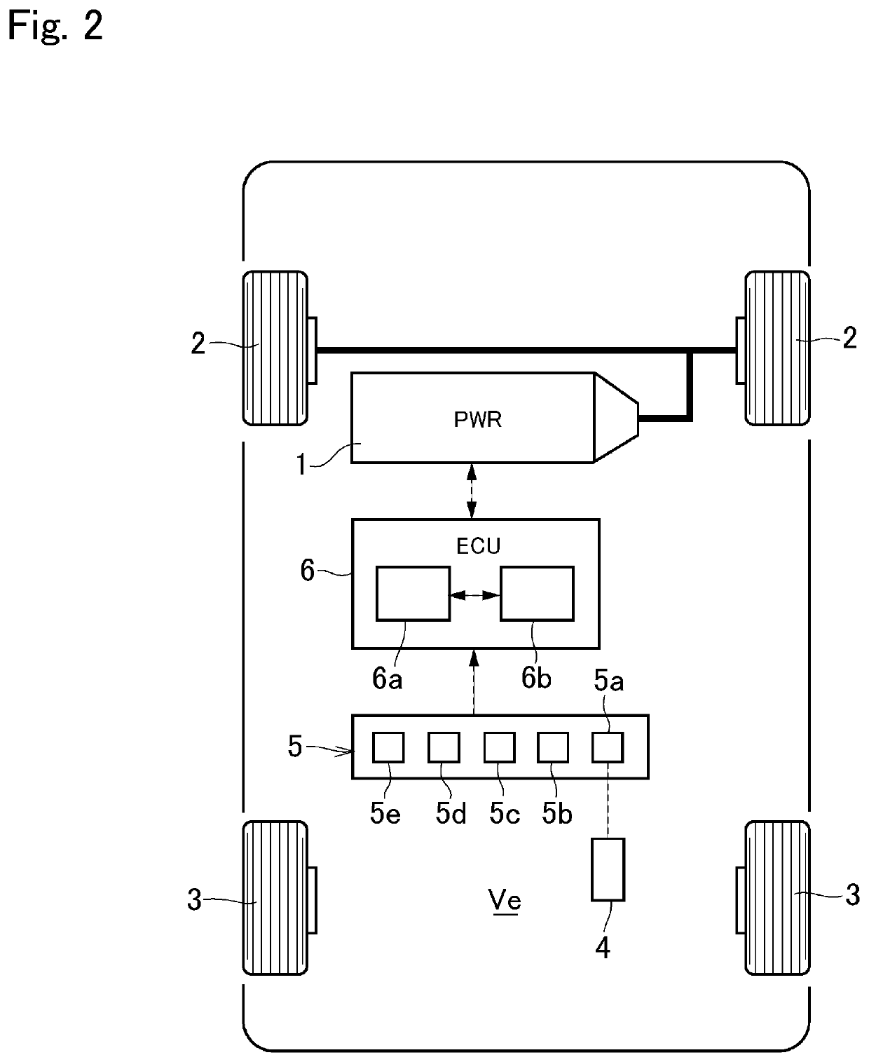
[0026]Referring now to FIG. 2, there is shown an example of a drive system of a vehicle Ve to which the control system according to the embodiment of the present invention is applied. The vehicle Ve illustrated in FIG. 2 comprises a prime mover (referred to as “PWR” in FIG. 1) 1, a pair of front wheels 2, a pair of rear wheels 3, an accelerator pedal 4, a detector 5, and a controller (referred to as “ECU” in FIG. 1) 6.

[0027]The prime mover 1 generates a drive torque to establish a driving force to propel the vehicle Ve. For example, an internal combustion engine such as a gasoline engine and a diesel engine may be adopted as the prime mover 1. An output power of the engine may be adjusted electrically, and the engine may be started and stoppe...


PUM


Abstract

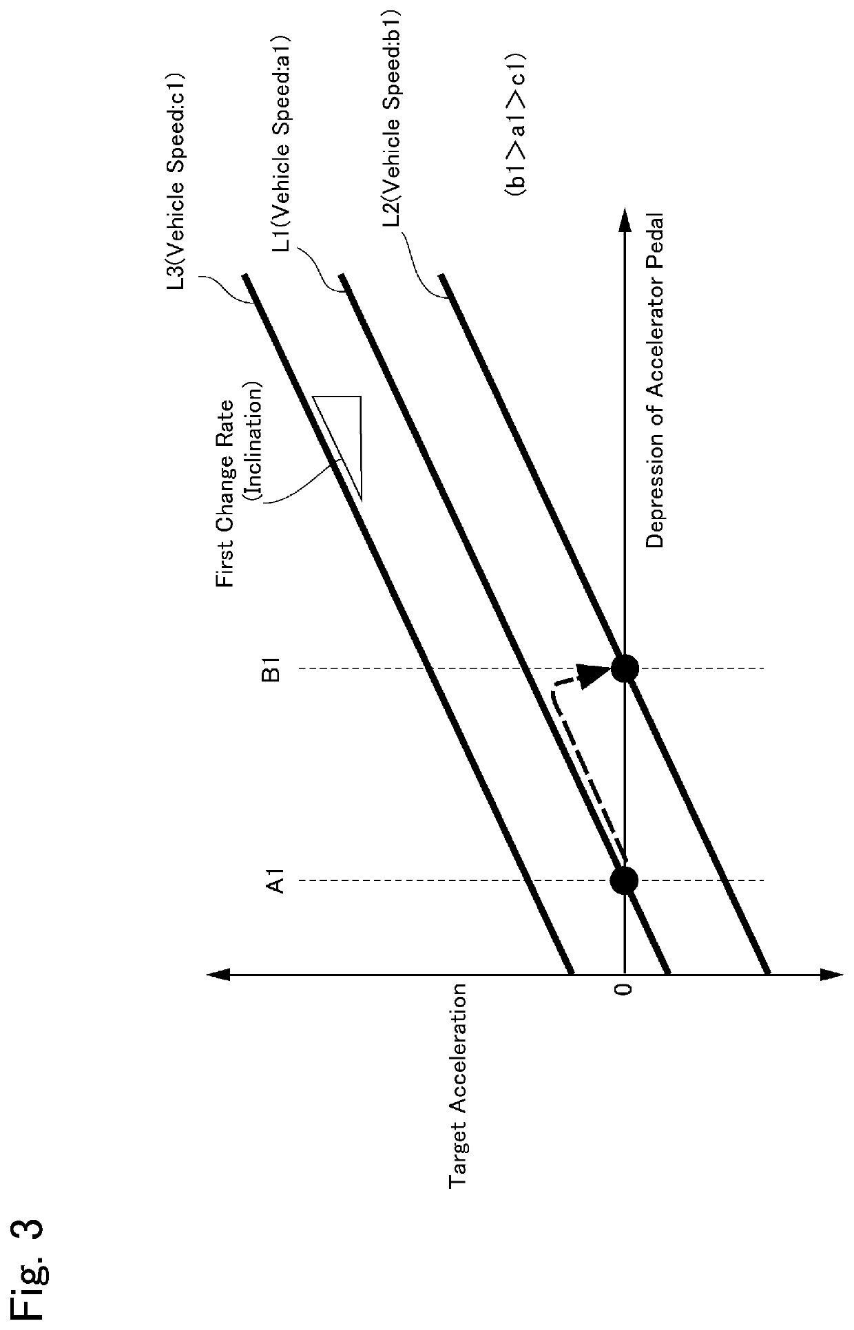
A vehicle control system configured to operate a vehicle in line with a driver's intention in respective operating mode. An operating mode of the vehicle is select from a normal mode in which a first acceleration characteristic is employed, and a sport mode in which a second acceleration characteristic to propel the vehicle in a dynamic manner is employed. In the normal mode, a controller increases a target acceleration with an increase in depression of an accelerator at a first change rate, and decreases the target acceleration with an increase in a vehicle speed at a second change rate. In the sport mode, the controller increases the target acceleration with an increase in depression of the accelerator at the first change rate, and decreases the target acceleration with an increase in the vehicle speed at a third change rate smaller than the second change rate.

Description

CROSS REFERENCE TO RELATED APPLICATIONS[0001]The present disclosure claims the benefit of Japanese Patent Application No. 2018-199180 filed on Oct. 23, 2018 with the Japanese Patent Office, the disclosure of which are incorporated herein by reference in its entirety.BACKGROUNDField of the Disclosure[0002]Embodiments of the present application relate to the art of a vehicle control system configured to set a target acceleration based on an accelerating operation executed by a driver.Discussion of the Related Art[0003]US 2015 / 019091 A1 describes a vehicle control system configured to set a target acceleration based on an accelerator angle. The vehicle control system taught by US 2015 / 019091 A1 is capable of selectively setting one of a normal-mode and a sport-mode as a vehicle travel mode. A difference between the sport-mode target acceleration and the normal-mode target acceleration becomes smaller along with an increase in the vehicle speed, when compared under the same condition in...

Claims


Application Information

Patent Timeline
Patent Type & Authority Applications(United States)
IPC IPC(8): B60W30/18B60W10/04B60W50/08
CPCB60W50/082B60W10/04B60W30/18B60W2520/105B60W2400/00B60W2720/106B60W30/182B60W40/10B60W40/105B60W2520/10B60W2540/10B60W2710/0666B60W2540/215B60W50/10
Inventor KANNO, YOSHIHITO
Owner TOYOTA JIDOSHA KK
Learn More