Vehicle-use speed control apparatus

a speed control and vehicle technology, applied in the direction of braking systems, process and machine control, instruments, etc., can solve the problems of inability to perform acceleration/deceleration control, awkward vehicle movement implemented by speed control, etc., to achieve smooth and comfortable control of vehicle speed.

Inactive Publication Date: 2011-11-17
DENSO CORP
View PDF14 Cites 13 Cited by
  • Summary
  • Abstract
  • Description
  • Claims
  • Application Information

AI Technical Summary

Benefits of technology

[0020]According to the present invention, there is provided a vehicle-use speed control device capable of controlling the speed of a vehicle smoothly and comfortably for the vehicle driver even when no preceding vehicle is present.

Problems solved by technology

However, in the apparatus disclosed in Patent document 3, if the vehicle driver's operation of the accelerator or brake is poor, the vehicle movement implemented by the speed control may become awkward.
This raises a problem that when there is no vehicle preceding the own vehicle, it is not possible to perform the acceleration / deceleration control.

Method used


Image

  • Vehicle-use speed control apparatus
  • Vehicle-use speed control apparatus
  • Vehicle-use speed control apparatus

Examples


first embodiment

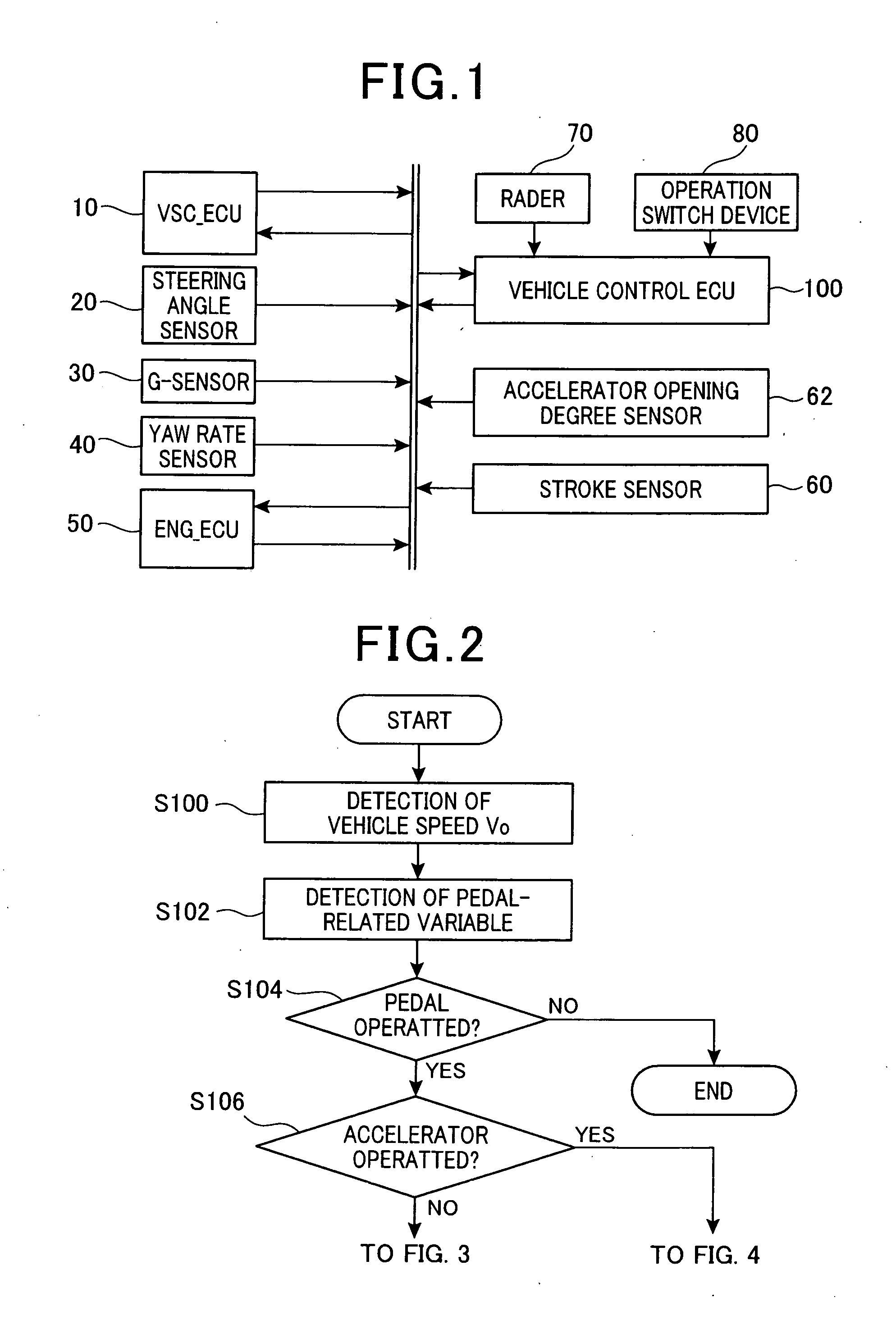
[0038]FIG. 1 is a diagram showing the overall structure of a drive support system including a vehicle control ECU 100 according to an embodiment of the invention. As shown in FIG. 1, the drive support system includes a VSC_ECU 10, a steering angle sensor 20, a G-sensor 30, a yaw rate sensor 40, an ENG_ECU 50, a stroke sensor 60, and accelerator opening degree sensor 62, a radar 70, an operation switch device 80 and the vehicle control ECU 100.

[0039]The VSC_ECU 10, which is for controlling a brake actuator (not shown) to apply a brake force to a vehicle on which the drive support system is mounted (may be referred to as the vehicle or the own vehicle hereinafter), includes a VSC (Vehicle Stability Control: registered trade mark) function to restrict the vehicle from skidding. The VSC_ECU 10 receives information regarding a target deceleration from an in-vehicle LAN, and controls the brake actuator in order that the vehicle decelerates at this target deceleration. The VSC_ECU 10 also ...

modification 1

[0093]In the above embodiment, when the accelerator pedal is operated, the target speed Vm is set in accordance with the relationship shown in FIG. 8, and it is determined whether the difference between the target speed Vm and the actual vehicle speed Vo (the relative speed Vr_p) has varied more than the threshold TH. If this determination is affirmative, the acceleration control is started, and otherwise, this determination is made again. In modification 1, even when this determination is negative, the acceleration control is performed so that the actual acceleration agrees with an acceleration set differently from the target acceleration (referred to as “set acceleration Gb” in the following) if the pedal-related variable is in an increasing trend.

[0094]The pedal-related variable may be the accelerator pedal opening degree, or the stroke amount of the accelerator pedal. In the following, a case where the accelerator pedal opening degree is used as the pedal-related variable is exp...

modification 2

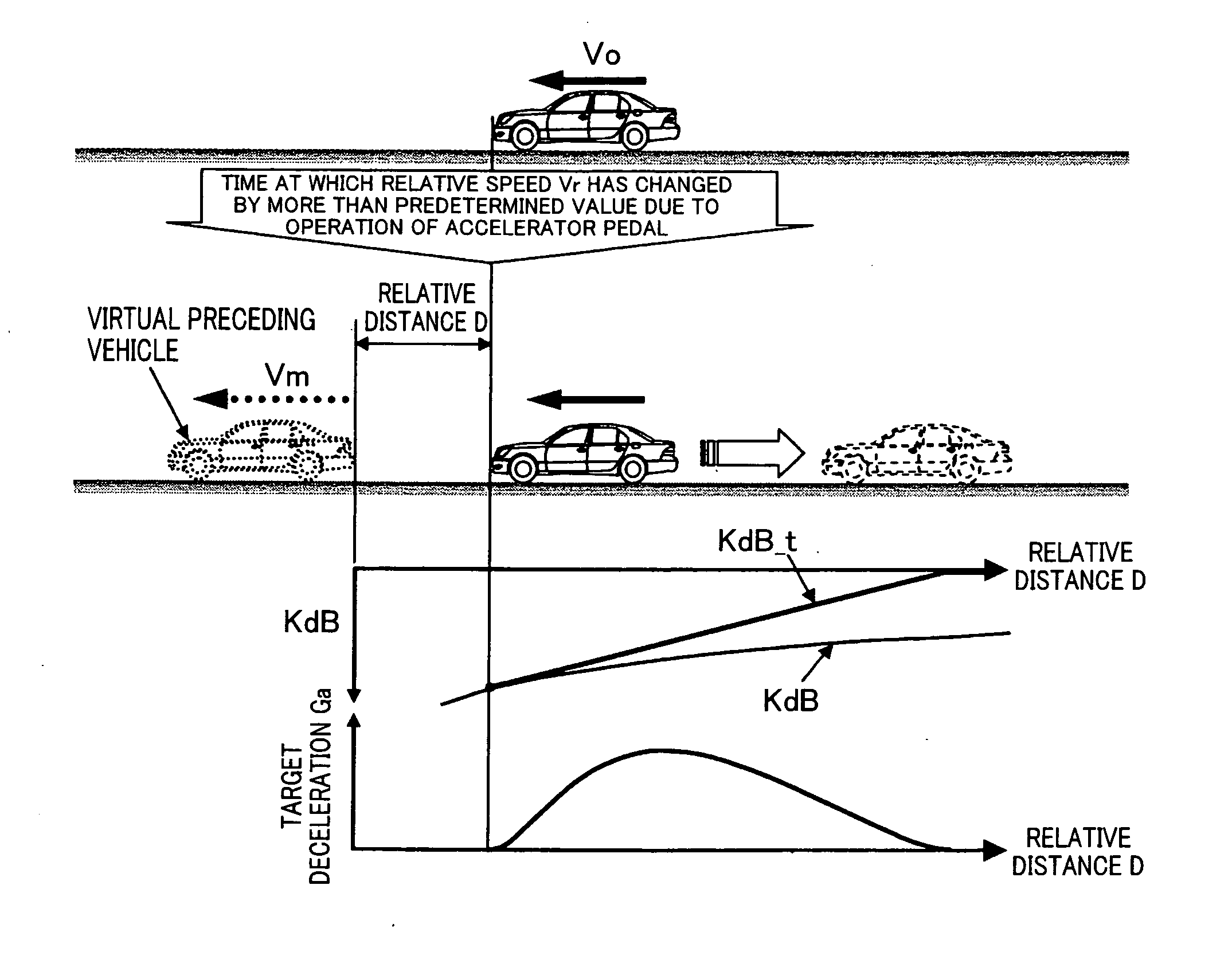
[0111]In the above embodiment, the target speed Vm is set based on the relationship shown in FIG. 5 or 8 when the accelerator pedal is operated, and the operation steps after the steps for setting the initial distance D(tbi) or D(tai) are performed based on the difference between the target speed Vm and the actual vehicle speed Vo (that is, the relative speed Vr_p). In modification 2, the operation steps after the steps for setting the initial distance D(tbi) or D(tai) are performed even when the target speed Vm does not change, that is, even when the depression amount of the accelerator pedal is constant, if the vehicle speed has varied by more than a predetermined value. To implement this, the vehicle speed Vo detected in step S114 or S142 may be used to calculate the relative speed Vr_p.


PUM


Abstract

The vehicle-use speed control apparatus sets a virtual preceding vehicle assumed to run at a target speed at a predetermined initial distance ahead of the own vehicle when the brake pedal is operated causing a relative speed between the actual vehicle speed and the target speed exceeds a predetermined value, calculates an initial value of a performance index for approach and alienation based on the initial distance and the target speed. Thereafter, the vehicle-use speed control apparatus repeatedly calculates a following distance to the virtual preceding vehicle based on a time elapsed from when a speed control condition is satisfied, the current relative speed and the initial distance, and a target relative speed based on the initial distance, the initial value of the performance index and the following distance, and controls the vehicle speed based on the difference between the target relative speed and the actual relative speed.

Description

[0001]This application claims priority to Japanese Patent Applications No. 2010-111414 filed on May 13, 2010, and No. 2010-234694 filed on Oct. 19, 2010, the entire contents of which are hereby incorporated by reference.BACKGROUND OF THE INVENTION[0002]1. Field of the Invention[0003]The present invention relates to a vehicle-use speed control apparatus.[0004]2. Description of Related Art[0005]There are known various vehicle-use speed control apparatuses including ones configured to perform speed control of a vehicle on which the vehicle-use speed control apparatus (may be referred to as “the own vehicle” hereinafter) in accordance with a performance index representing a state of approach or alienation (separation) between the own vehicle and a preceding vehicle (may be referred to simply as “performance index” hereinafter), and a relational expression of performance index for approach and alienation, showing a relationship between the distance to the preceding vehicle and the relati...

Claims


Application Information

Patent Timeline
Patent Type & Authority Applications(United States)
IPC IPC(8): B60K31/00B60T7/12B60T8/32B60W10/04B60W10/184B60W30/14B60W30/16B60W40/04F02D29/02
CPCB60W30/16B60W2520/10B60W2550/302B60W2550/308B60W2720/106B60W30/162B60W30/165G08G1/163B60W30/143B60W30/146G08G1/16B60W2554/804B60W2554/801
Inventor ISAJI, KAZUYOSHITSURU, NAOHIKO
Owner DENSO CORP
Why Eureka
Try Eureka