
Dynamic noise filter and sigma filtering method

a filtering method and noise filter technology, applied in the field of noise filtering, can solve the problems of unstable output image quality, lowering image quality, and complicated image contents, and achieve the effect of filtering out noise and best image quality

Inactive Publication Date: 2010-07-29
SILICON INTEGRATED SYSTEMS
View PDF5 Cites 14 Cited by
  • Summary
  • Abstract
  • Description
  • Claims
  • Application Information

AI Technical Summary

Benefits of technology

[0014]In view of the above-mentioned problems, one object of the invention is to provide a dynamic noise filter to dynamically modify the strengths of the SNR filter and the TNR filter and to dynamically modify a blending ratio between the output of the SNR filter and the output of the TNR filter by performing noise estimation for each image to thereby filter out noise and obtain the best image quality.

Problems solved by technology

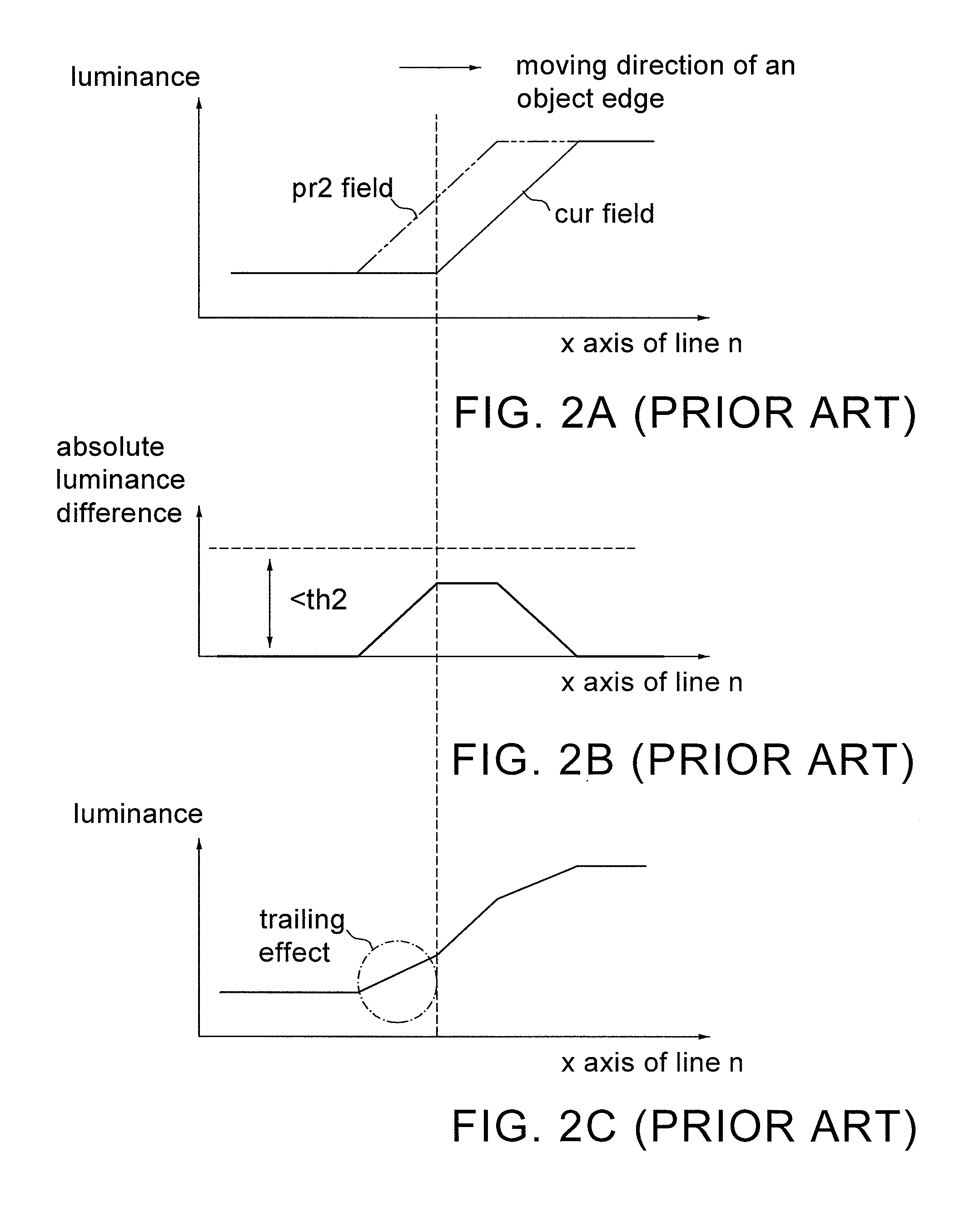
However, in practice, image contents are quite complicated; for example, there are different noise levels, different amounts of movement for different object, or different values of luminance difference between its objects and its backgrounds for each field.
Accordingly, no matter which filter (a TNR filter or a SNR filter) is applied, one single preset characteristic curve or a set of parameters is insufficient to cover all the image contents, thereby lowering the image quality.
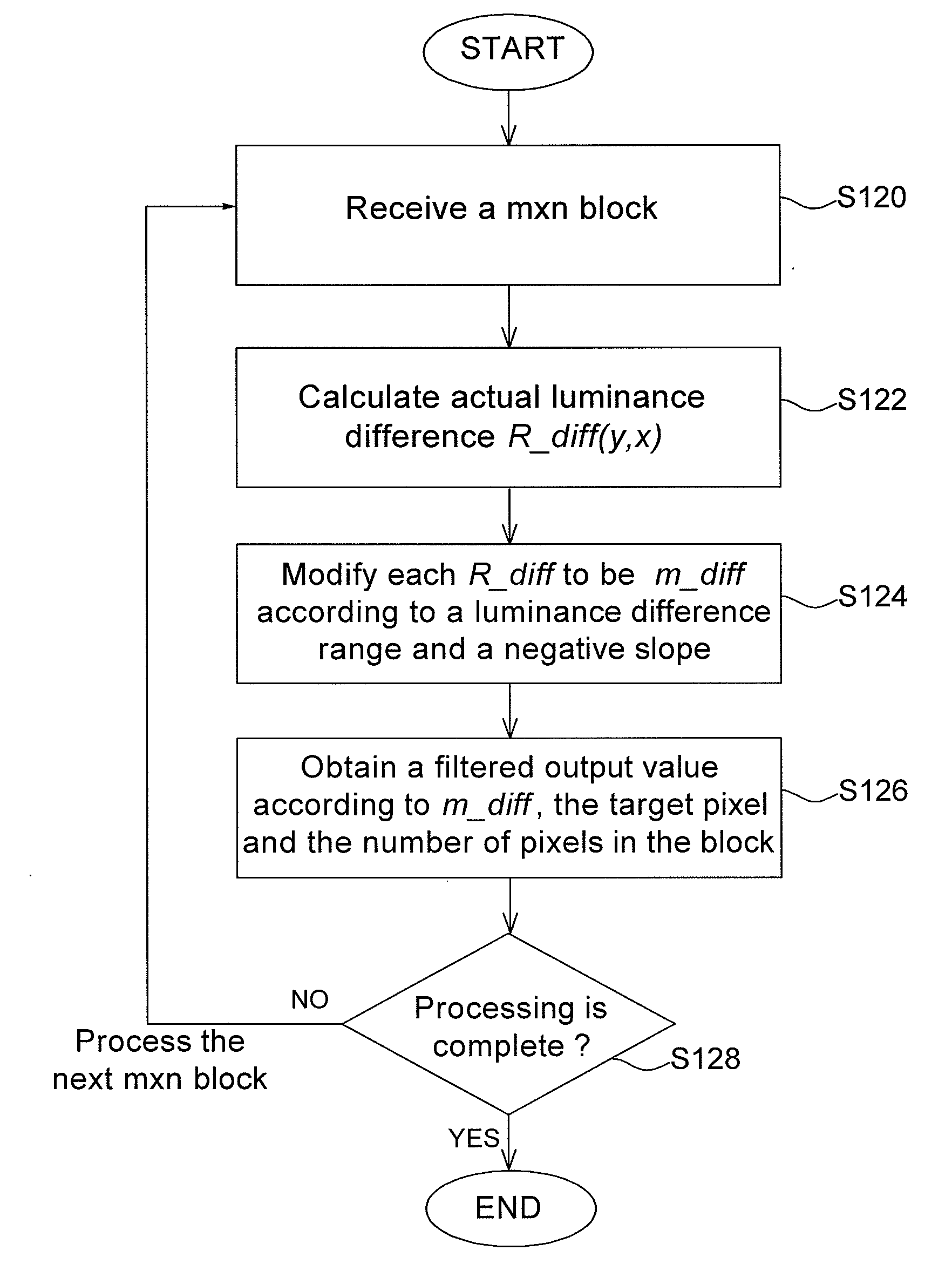
From the above example, when there is some noise in the 1×5 block, a luminance difference of six grey levels (from 14 to 20) is produced at the output of the sigma filter according to the slope slope2=∞ in FIG. 5B and the target pixel, thereby rendering the output image quality unstable.

Method used


Image

  • Dynamic noise filter and sigma filtering method
  • Dynamic noise filter and sigma filtering method
  • Dynamic noise filter and sigma filtering method

Examples


Embodiment Construction

[0051]The noise filter according to the invention may be hardware, software, or a combination of hardware and software (or firmware). An example of a pure solution would be a field programmable gate array (FPGA) design or an application specific integrated circuit (ASIC) design. An example of a hardware and software implementation would be a digital signal processor (DSP) and embedded firmware.

[0052]FIG. 6A shows a schematic diagram of a dynamic noise filter according to one embodiment of the invention. Referring to FIG. 6A, the dynamic noise filter 600 according to the invention comprises a noise estimation circuit 610, a TNR filter 620, a SNR filter 630, a blending circuit 640, and a motion estimation circuit 650. In this embodiment, the noise estimation circuit 610 simultaneously receives three scan lines C(i−1), C(i), and C(i+1) of the cur field and three scan lines P(i−1), P(i), and P(i+1) of the pre2 field to perform noise estimation and thereby generates a temporal attribute ...


PUM


Abstract

A dynamic noise filter is disclosed, which includes a noise estimation circuit, a TNR filtering circuit, a SNR filtering circuit, a blending circuit and a motion estimation circuit. By performing noise estimation for each image, the invention dynamically adjusts the strengths of the TNR filter and the SNR filter as well as a blending ratio between the outputs of the TNR filter and the SNR filter, thereby obtaining the best image quality.

Description

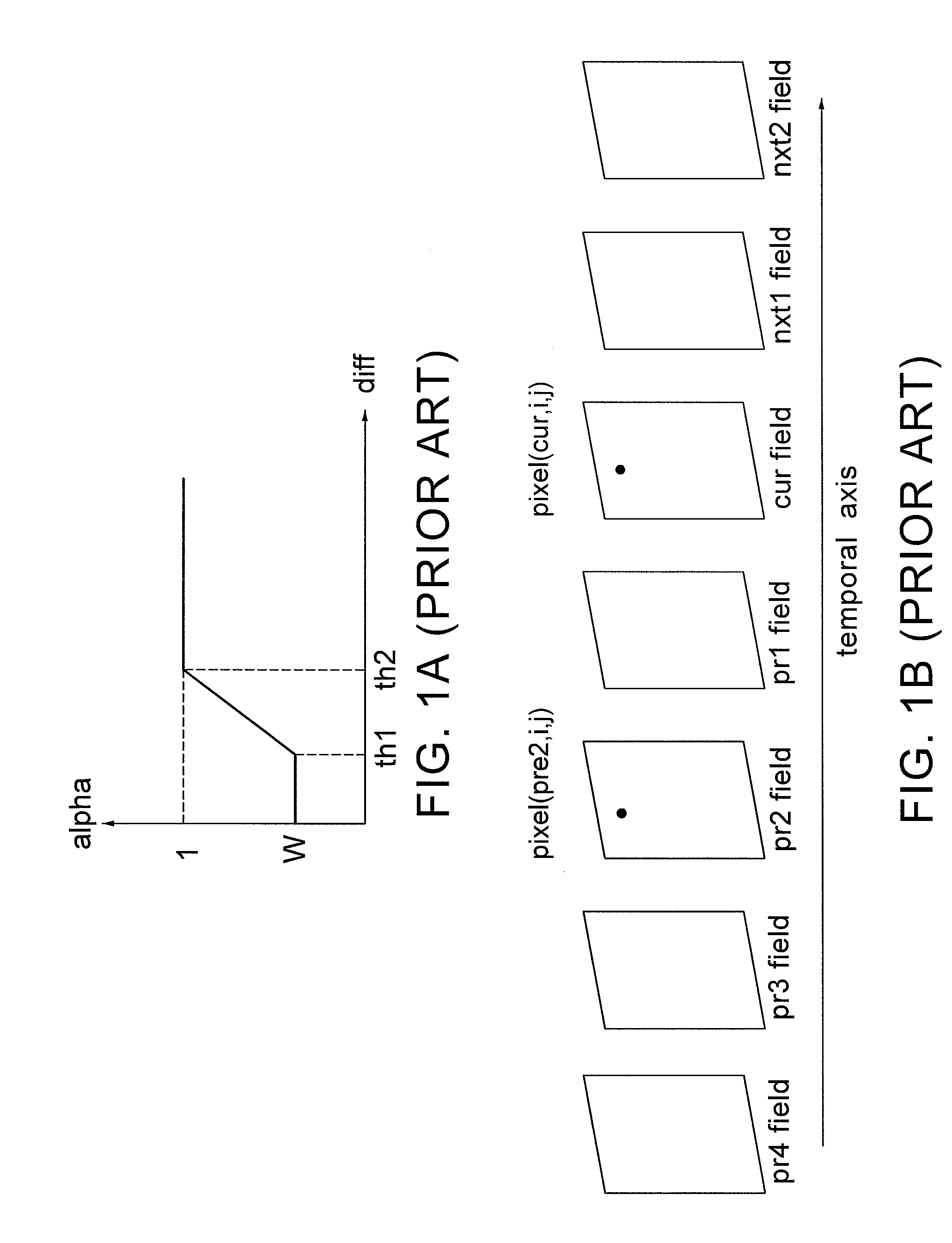
[0001]This application claims the benefit of the filing date of Taiwan Application Ser. No. 098102693, filed on Jan. 23, 2009, the content of which is incorporated herein by reference.BACKGROUND OF THE INVENTION[0002]1. Field of the invention[0003]The invention relates to a noise filter, particularly to a dynamic noise filter.[0004]2. Description of the Related Art[0005]FIG. 1A shows a characteristic curve of a temporal noise reduction (TNR) filter in the prior art. FIG. 1B shows the relationship of continuous fields versus a temporal axis.[0006]Noise reduction of image data is generally realizes through averaging likely correlated pixels. Referring to FIGS. 1A and 1B, for example, among interlaced fields sequentially arranged in a temporal axis, the TNR filter compares the luminance of one single pixel (assuming a pixel pixel(cur, i, j) at the coordinate (i,j) of the current field, called “cur field”) with the luminance of the pixel pixel(pre2, i, j) at the same coordinate (i,j) of...

Claims


Application Information

Patent Timeline
Patent Type & Authority Applications(United States)
IPC IPC(8): H04N5/00G06K9/36
CPCH04N5/213H04N5/145
Inventor HSU, JENG-YUN
Owner SILICON INTEGRATED SYSTEMS
Learn More