Watch with calendar mechanism having two date indicators

a technology of a calendar mechanism and a date indicator, which is applied in the direction of mechanical clocks, instruments, and can solve the problems of excessive rotation of the first date indicator, limitation of the position at which the two rotary members can display the date, and inability to arrange the 1-place rotary member and the 10-place rotary member, etc., to achieve the effect of satisfying the operability, reliably displaying the date, and small thickness

Inactive Publication Date: 2010-07-29
SEIKO INSTR INC
View PDF6 Cites 34 Cited by
  • Summary
  • Abstract
  • Description
  • Claims
  • Application Information

AI Technical Summary

Benefits of technology

[0027]According to the present invention, there is provided a watch with a calendar mechanism including a first date indicator displaying the 1 place of a date and a second date indicator displaying the 10 place of a date, wherein there is involved no increase in the number of times that the calendar mechanism has to be corrected at month ends, thus providing a satisfactory operability. Further, the watch with a calendar mechanism of the present invention is capable of reliably displaying dates in large letters, small in thickness, and little restricted in terms of design. Further, in the watch with a calendar mechanism of the present invention, when the user rotates the crown to perform date display correction, it is possible to prevent occurrence of excessive rotation of the second date indicator, and there is no fear of the first date indicator and the second date indicator becoming out of phase with each other.

Problems solved by technology

However, in the first type of conventional watch with a calendar mechanism, the 1-place rotary member directly rotates the 10-place rotary member, so that it is impossible to arrange the 1-place rotary member and the 10-place rotary member such that they share the same rotation center.
Thus, in designing the two rotary members, there are limitations regarding the position at which display of date is possible by the two rotary members.
In the second type of conventional watch with a calendar mechanism, there is a fear of the first date indicator being excessively rotated when correcting date to make first date indicator and the second date indicator out of phase with each other.
In this construction, there is a fear of correct date display being impossible.
Thus, in the third type of conventional watch with a calendar mechanism, it is necessary to increase the operational force applied to the train wheel for feeding the date indicators, resulting in an increase in the size and thickness of the watch.
The third type of conventional watch with a calendar mechanism includes a step motor and an ultrasonic motor, so that the date feeding mechanism is rather thick, and the motor driving circuit is complicated, with the IC size being rather large, which makes it necessary to provide a large number of electronic components.
When the jumper follows the tooth portion when the user rotates the crown to correct the date display, the protruding element does not come into contact with the slider outer wall, and there is a fear of occurrence of excessive rotation (that is, the date display moving body carrying the number group arrangement is allowed to make excessive rotation due to the inertia during rotation, i.e., so-called “over-rotation”).

Method used


Image

  • Watch with calendar mechanism having two date indicators
  • Watch with calendar mechanism having two date indicators
  • Watch with calendar mechanism having two date indicators

Examples


first embodiment

(1) First Embodiment

[0053]In the following, a watch with a calendar mechanism according to the first embodiment of the present invention will be described with reference to the drawings. In the embodiment described below, the watch with a calendar mechanism is formed as a mechanical watch. While in the following the watch with a calendar mechanism of the present description is described as applied to a mechanical watch, the present invention is applicable not only to a mechanical watch but also to an analog electronic watch. That is, in this specification, the concept of “watch with a calendar mechanism” is a concept that also includes an “analog electronic watch” and analog watches of all the other operating principles.

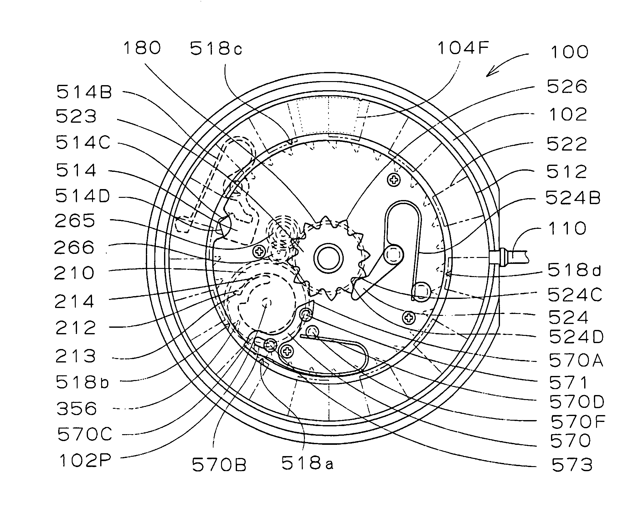
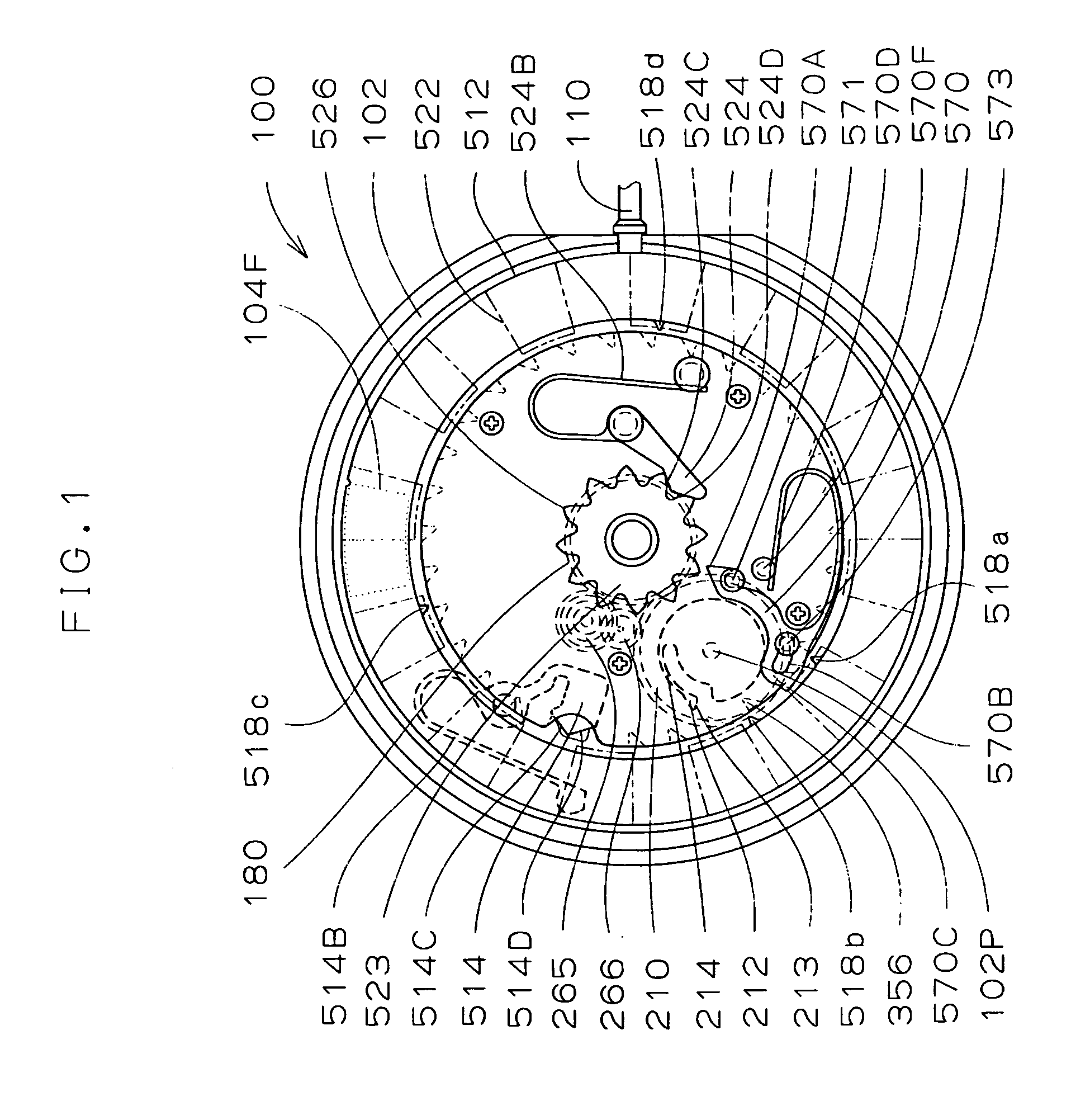
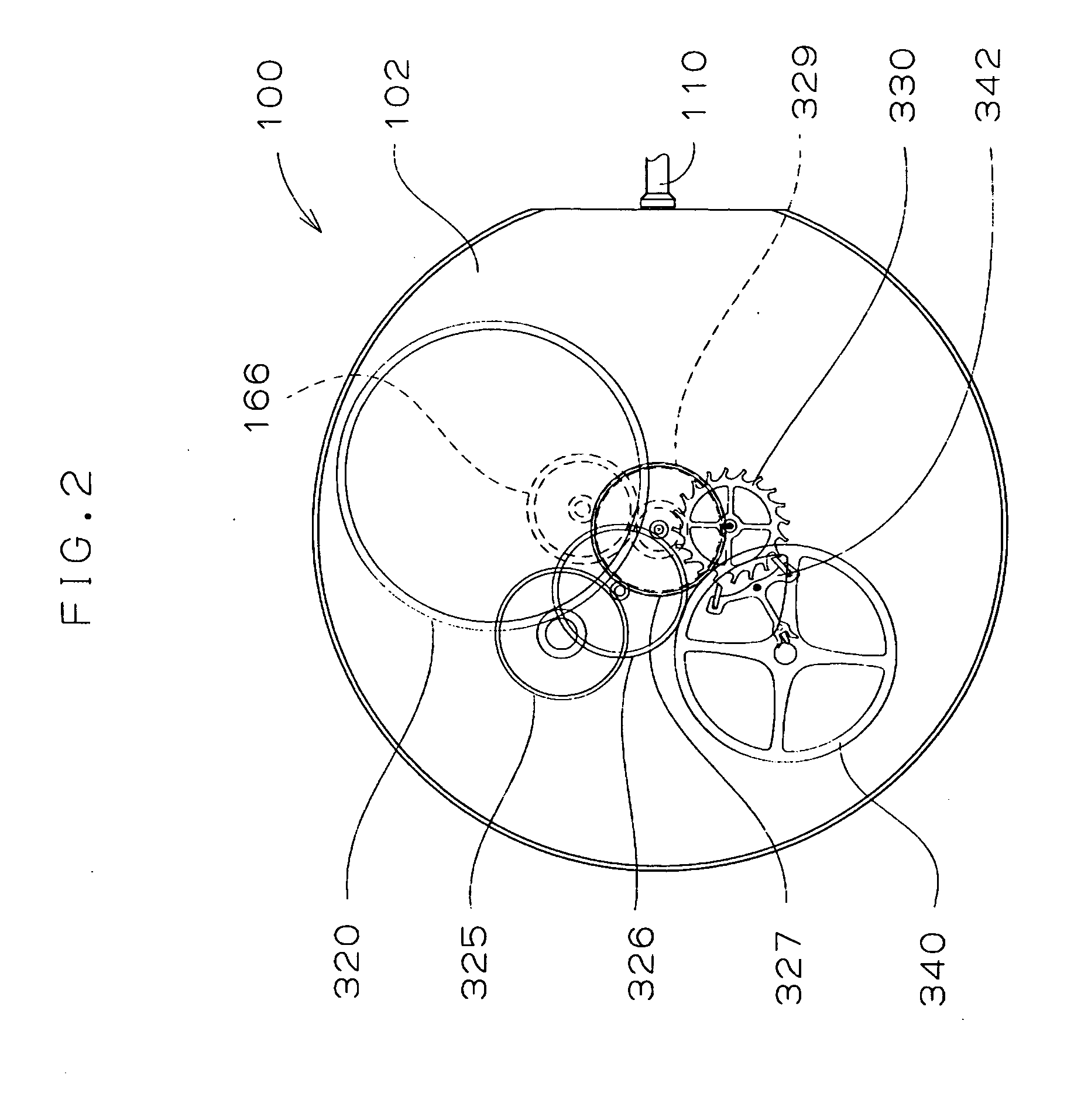
[0054](1.1) General Construction of the Movement:

[0055]Referring to FIGS. 1 through 3 and 22, a movement 100 is formed by a mechanical watch. The movement 100 includes a main plate 102 constituting the base plate of the movement 100. A dial 104 is mounted to the glas...

second embodiment

(2) Second Embodiment

[0144]Next, a watch with a calendar mechanism according to a second embodiment of the present invention will be described. In the following, the differences between the watch with a calendar mechanism of the second embodiment of the present invention and the watch with a calendar mechanism of the first embodiment of the present invention will be mainly described. Thus, in the following, where there is no corresponding description, the above description of the watch with a calendar mechanism of the first embodiment of the present invention is applicable.

[0145]Referring to FIG. 19, the second date indicator feeding lever 570 has moved to a maximum degree toward a tooth portion 566 of the second date star 523 of the second date indicator 562. Referring to FIG. 20, through further rotation of the date feeding finger 212, the first date indicator 552 has been rotated one pitch counterclockwise by the force of the first date jumper 514. Referring to FIG. 23, in a move...

third embodiment

(3) Third Embodiment

[0149]Next, a watch with a calendar mechanism according to a third embodiment of the present invention will be described. In the following, the differences between the watch with a calendar mechanism of the third embodiment of the present invention and the watch with a calendar mechanism of the first embodiment of the present invention will be mainly described. Thus, in the following, where there is no corresponding description, the above description of the watch with a calendar mechanism of the first embodiment of the present invention is applicable. The watch with a calendar mechanism of the third embodiment of the present invention consists of an analog electronic watch. In applying the present invention to an analog electronic watch, the construction and operation of the switching mechanism, the calendar feeding mechanism, and the calendar correction mechanism are the same as those of the first embodiment described above.

[0150]Referring to FIG. 25, a movement...


PUM


Abstract

The present invention aims to provide a watch with a calendar mechanism which has a first date indicator and a second date indicator and which is of a satisfactory operability. The watch with a calendar mechanism of the present invention is equipped with a second date indicator feeding lever adapted to move based on the rotation of the first date indicator and to rotate the second date indicator. The first date indicator includes first date indicator tooth portions, and calendar shift teeth. The calendar shift teeth consist of a first calendar shift tooth, a second calendar shift tooth formed at an interval of (360*2/31) degrees in a first direction using the first calendar shift tooth as a reference, a third calendar shift tooth formed at an interval of (360*9/31) degrees in the first direction using the second calendar shift tooth as a reference, and a fourth calendar shift tooth formed at an interval of (360*10/31) degrees in a direction opposite to the first direction using the first calendar shift tooth as a reference.

Description

BACKGROUND OF THE INVENTION[0001]1. Field of the Invention[0002]The present invention relates to a watch with a calendar mechanism including a first date indicator indicating the one place of a date and a second date indicator indicating the ten place of a date.[0003]2. Description of the Related Art[0004]The mechanical structure including the driving portion of a watch is generally referred to as the “movement.” What is obtained by mounting a dial and hands to the movement and putting it into a watch case to attain a complete whole is referred to as the “complete” of a watch. Of the two sides of a main plate constituting the base plate of a watch, the side where the glass of the watch case is provided, that is, the side where the dial exists, is referred to as the “back, side” or the “glass side” or the “dial side” of the movement. Of the two sides of the main plate, the side where the case back of the watch case exists, that is, the side opposite to the dial, is referred to as the...

Claims


Application Information

Patent Timeline
Patent Type & Authority Applications(United States)
IPC IPC(8): G04B19/247G04B19/24
CPCG04B19/25366
Inventor WATANABE, MAMORU
Owner SEIKO INSTR INC
Why Eureka
Try Eureka