Method of Segmenting Anatomic Entities in 3D Digital Medical Images

Active Publication Date: 2010-07-29
AGFA NV
View PDF2 Cites 54 Cited by
  • Summary
  • Abstract
  • Description
  • Claims
  • Application Information

AI Technical Summary

Benefits of technology

[0057]In order to compare a profile with another profile, it is necessary to know how each point in the profile relates to any other point, and to measure the extent by which the value of a certain point of the profile varies from the mean with respect to any of the other points. This statistical relationship is captured by the covariance measure, which is always computed between 2 points (or the features at those points). If the covariance is measured between the feature value of a point and itself, the variance is obtained. When the profile consists of k points at either side of the contour, for a total of 2k+1 points, (2k+1)k number of relationships exists. The covariance between a pair of points from the profile tells the way how a first value of the pair varies with respect to the second. When the covariance is large and positive, it indicates that when the first point's feature value increases, so does the second in a proportional way. When the covariance is large and negative, it indicates that when the first point's feature value increases, the second decreases in a proportional way. When the covariance is zero, it means that there i

Problems solved by technology

Despite the poor performance of these low-level approaches, they are very popular in most commercial image analysis tools.
For complex image data however, such as present in medical images and exemplified by the content of a thorax image as described above, their usefulness is limited.
Unfortunately, the template matching is likely to fail in case of medical images.
Press, Cambridge, U.K. 1999) are able to cope with a larger shape variability, but are still unsuited for many medical segmentation tasks because little a priori knowledge about the object to be segmented can be incorporated.
Handcrafted parametric models overcome thi

Method used


Image

  • Method of Segmenting Anatomic Entities in 3D Digital Medical Images
  • Method of Segmenting Anatomic Entities in 3D Digital Medical Images
  • Method of Segmenting Anatomic Entities in 3D Digital Medical Images

Examples


Embodiment Construction

[0095]The present invention will be explained in detail with regard to a specific application, namely the segmentation of the lung field in a medical image.

[0096]Object Representation

[0097]In the specific embodiments of the method of the present invention that are described below, an anatomical object in an image is represented mathematically as a fixed number of discrete, labeled points lying on the contour that encloses the object, i.e. p1=(x1,y1), . . . , pn=(xn,un).

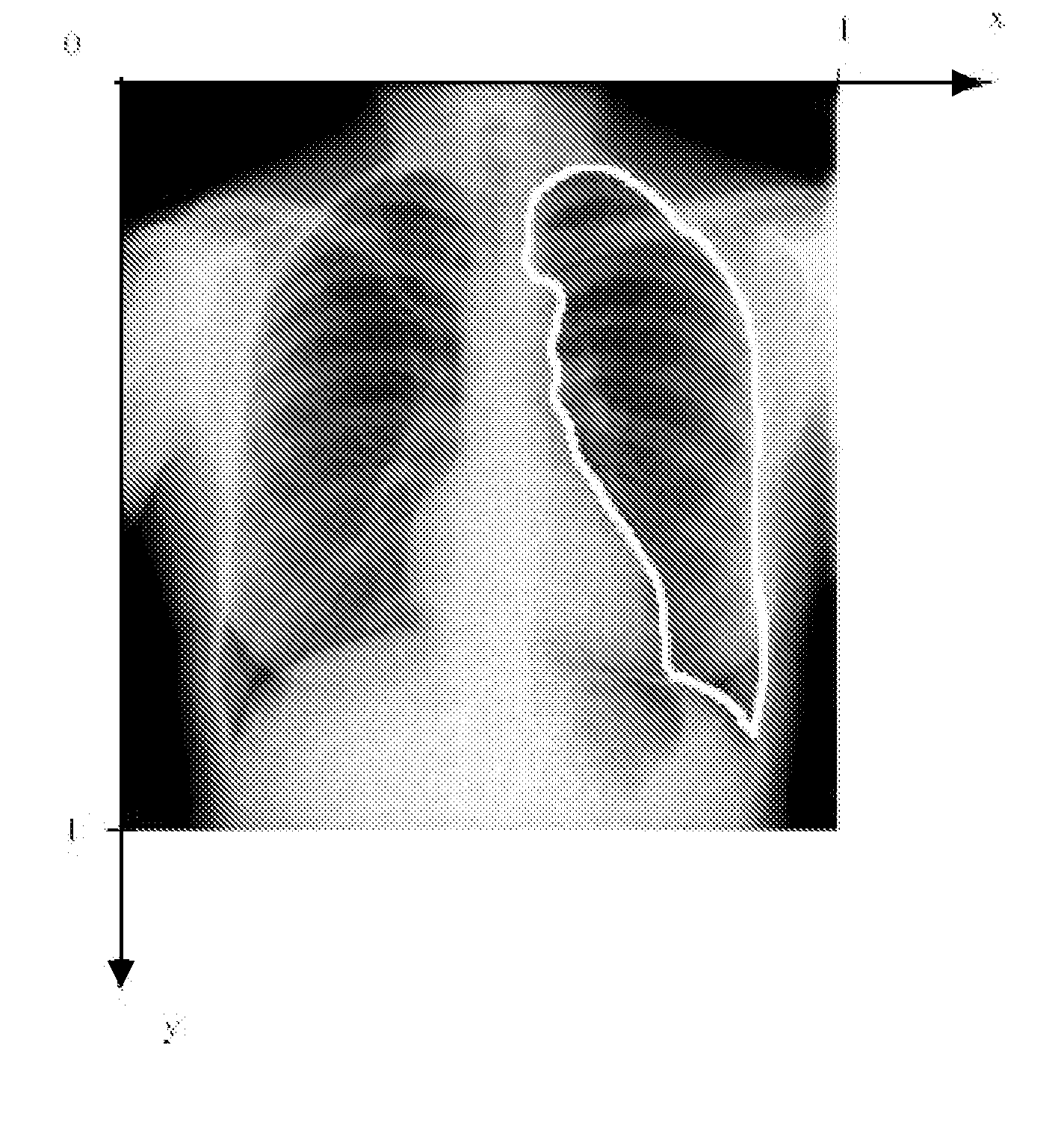
[0098]The contour{pi}i1n runs from p1 to pnand back to p1. Hence, the object may be captured by a discrete shape vector x=(x1,y1, . . . , xn,yn)T. The coordinate system is chosen such that all points inside the image area lie in the domain [0,1]x[0,1] (FIG. 7).

[0099]Additionally, characteristic points lying in the region enclosed by the contour may be added to the object representation as well, allowing e.g. measurement of entities lying inside the object.

[0100]The segmentation scheme described below needs a number of...


PUM


Abstract

For each of a number of landmarks in an image an initial position of the landmark is defined. Next a neighborhood around the initial position comprising a number of candidate locations of the landmark, is sampled and a cost is associated with each of the candidate locations. A cost function expressing a weighted sum of overall gray level cost and overall shape cost for all candidate locations is optimized. A segmented anatomic entity is defined as a path through a selected combination of candidate locations for which combination the cost function is optimized. During optimization towards the optimal segmented surface/volume graph traversal methods are exploited.

Description

FIELD OF THE INVENTION[0001]The present invention relates to a method of segmenting an entity in a digital image, more specifically an anatomic entity in a digital medical image. The segmentation process according to the present invention is based on the use of geometric and photometric models of an image.[0002]The method of the present invention can inter alia be used as a process of performing geometric measurements on digital images, more specifically on digital medical images.BACKGROUND OF THE INVENTION[0003]In radiological practice, geometric measurements are frequently used to aid diagnosis of abnormalities. In order to perform these measurements, key user points must be placed in an image, for example in an image displayed on a display device, on their corresponding anatomical landmark position. Measurements such as the distance between two points, or the angulation between lines are based on the position of these key user points. Furthermore, the geometry as a whole may be a...

Claims


Application Information

Patent Timeline
IPC IPC(8): G06K9/34G06K9/00
CPCG06T7/0081G06T7/0093G06T2207/30004G06T2207/10072G06T7/0095G06T7/11G06T7/162G06T7/168
Inventor DEWAELE, PIET
Owner AGFA NV
Why Eureka
Try Eureka