Battery assembly manufacturing method

a battery and assembly technology, applied in the direction of batteries, sustainable manufacturing/processing, wound/folded electrode electrodes, etc., to achieve the effect of uniform thickness, and reducing the spread of the thickness of the unit cell

Inactive Publication Date: 2010-07-29
TOYOTA JIDOSHA KK
View PDF8 Cites 94 Cited by
  • Summary
  • Abstract
  • Description
  • Claims
  • Application Information

AI Technical Summary

Benefits of technology

[0010]Accordingly, it is an object of the present invention to provide a method for manufacturing with good efficiency a battery assembly in which a plurality of unit cells are bundled by the preset (stipulated) bundling pressure and which has a preset accurate size (in particular, a length dimension of the battery assembly in the stacking direction of the unit cells constituting the battery assembly). Another object of the present invention is to provide a battery assembly obtained by this manufacturing method and a vehicle provided with the battery assembly.

Problems solved by technology

In addition to a limited installation space, battery assemblies that are installed on vehicles such as automobiles are presumed to be used in a state in which vibrations are generated.
When the battery assemblies are installed on vehicles, this spread in the stacking direction length (outer size) of the battery assemblies causes inconveniences, for example, the battery assembly cannot be accommodated in the installation space that has been prepared in advance or an extra gap remains when the battery assembly is accommodated in the gap.

Method used


Image

  • Battery assembly manufacturing method
  • Battery assembly manufacturing method
  • Battery assembly manufacturing method

Examples


example 1

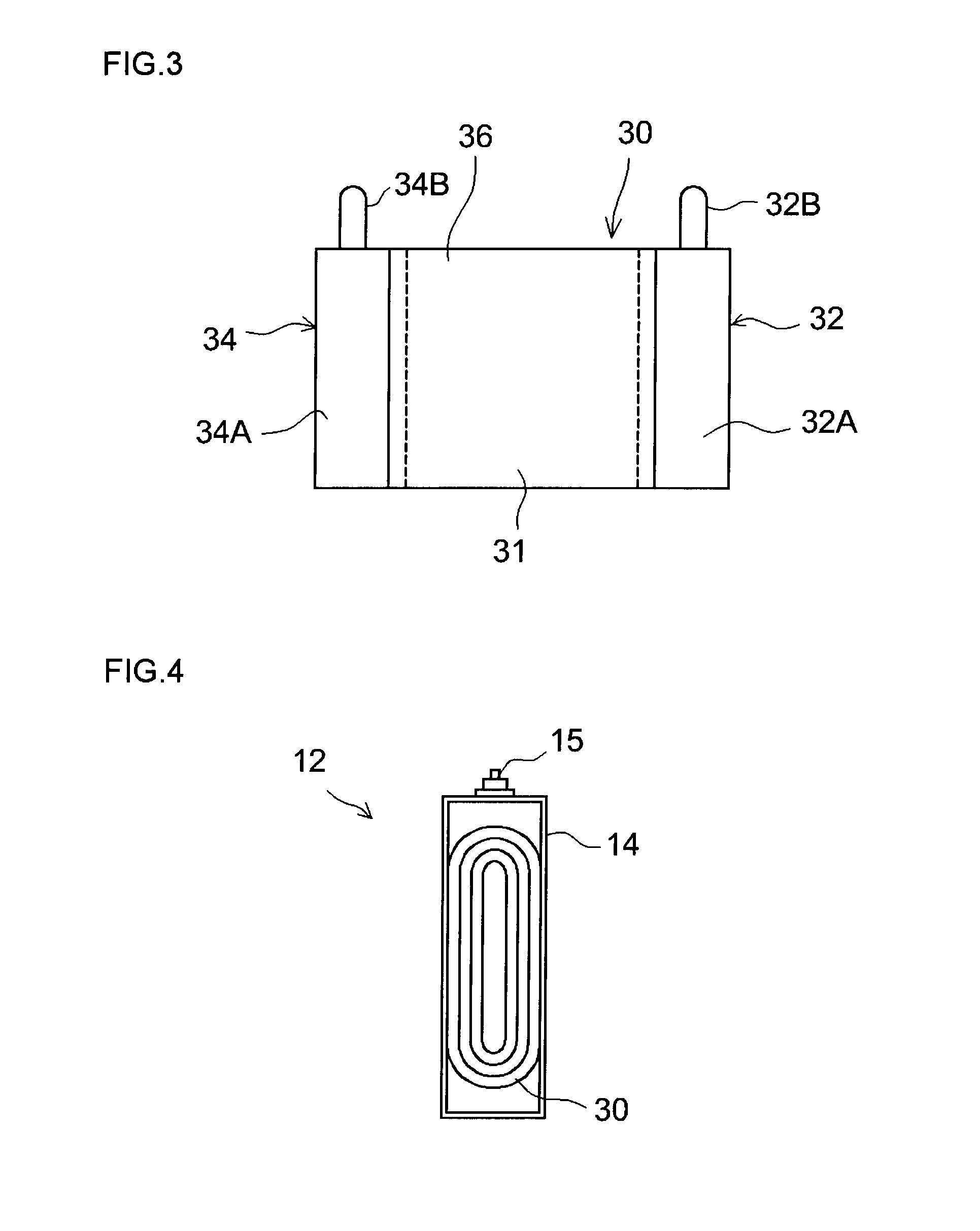
[0054]Similarly to a unit cell provided in the conventional battery assembly, a unit cell used as a constituent element of the battery assembly manufactured in each of the below-described embodiments typically includes an electrode body composed of predetermined constituent material of the battery (active materials of positive and negative electrodes, collectors of positive and negative electrodes, separator, etc.) and a container that accommodates the electrode body and an appropriate electrolyte.

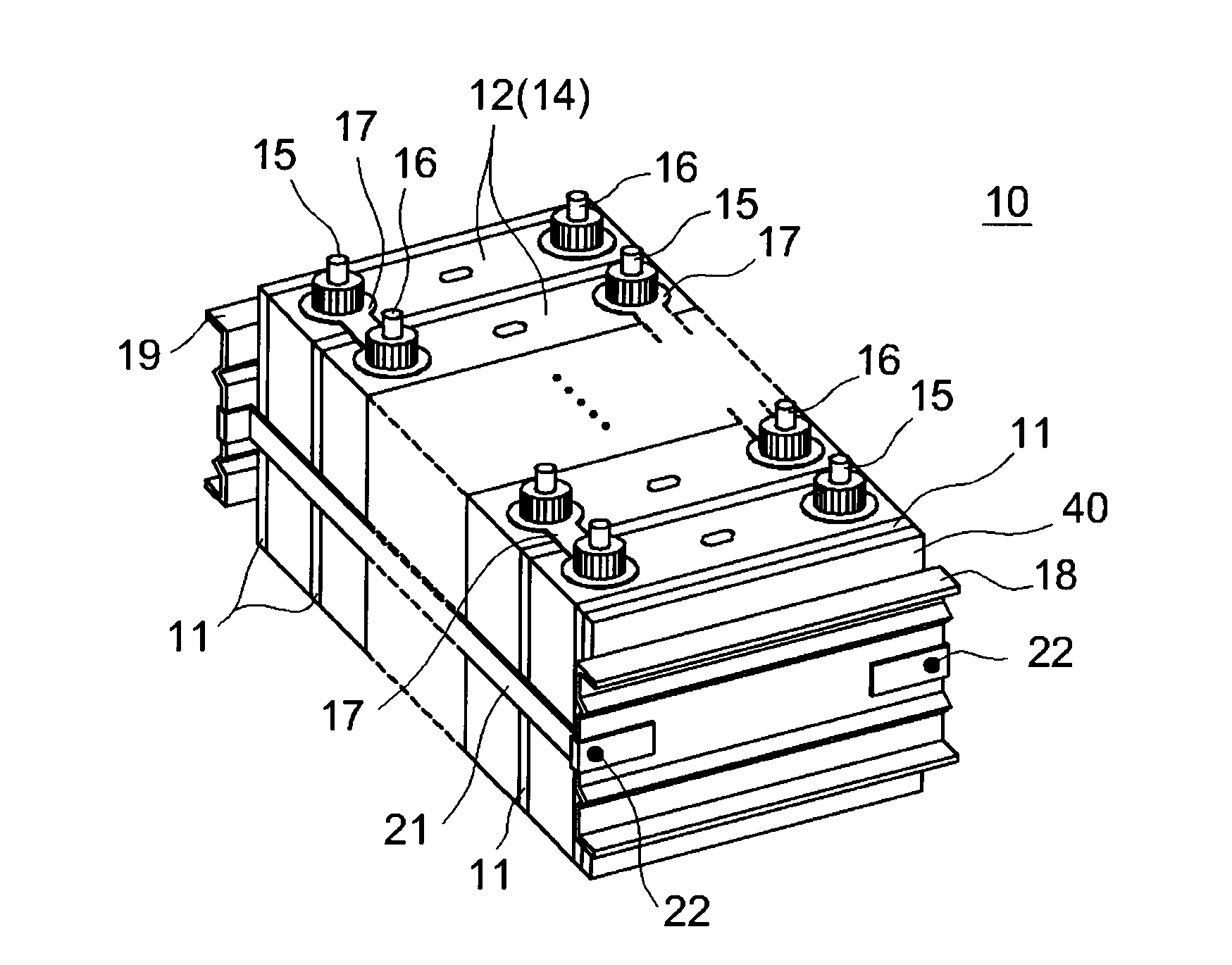
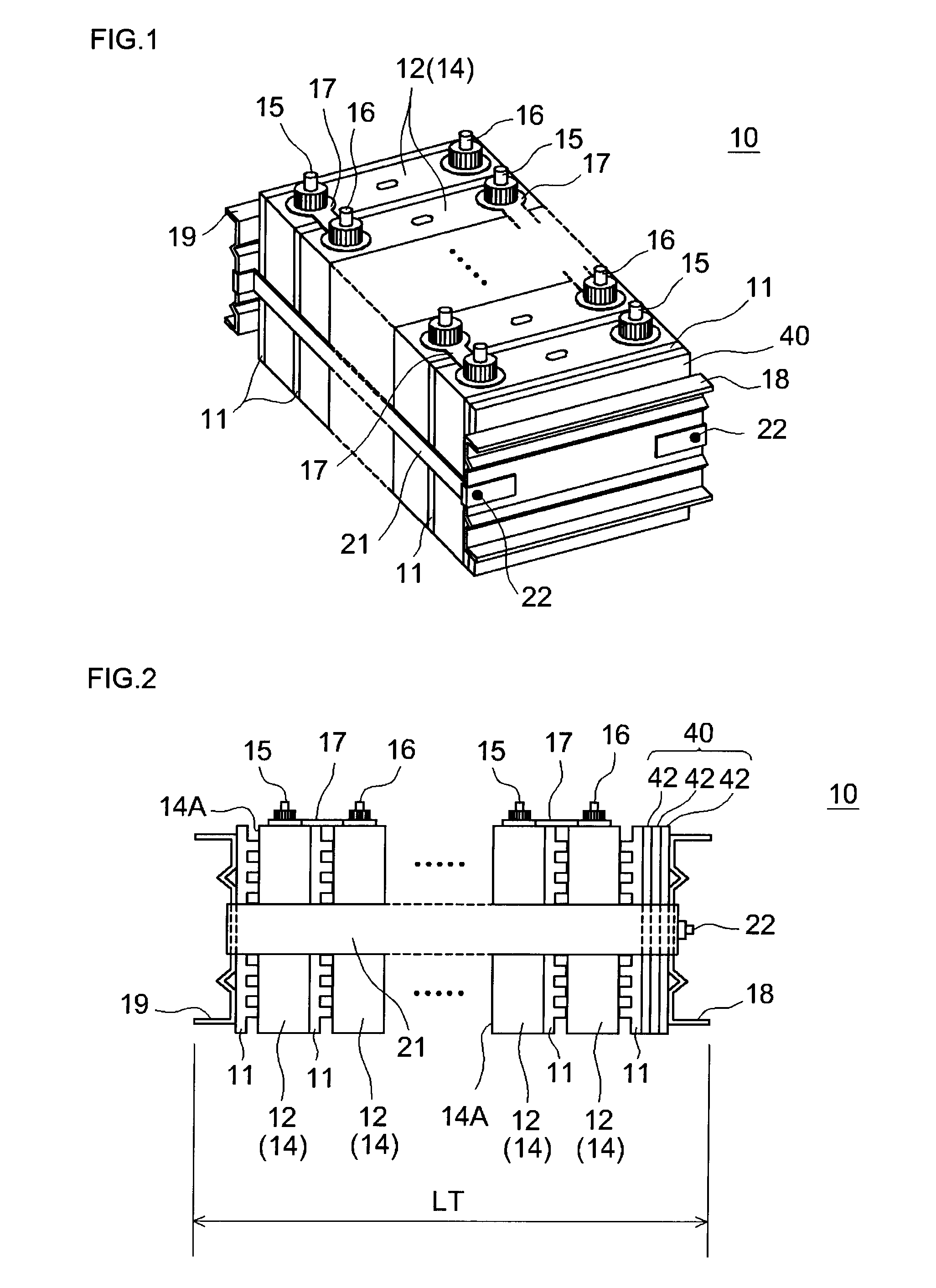
[0055]As an example, as shown in FIG. 1 and FIG. 2, a battery assembly 10 of the present example includes a predetermined number (typically 10 or more, preferably about 10 to 30, for example, 20) unit cells 12 of the same shape. The unit cell 12 has a container 14 of a shape (in the present embodiment, a flat box-like shape) that can accommodate the below-described flat-shaped wound electrode body. The “same shape” of the unit cells 12 means that the cells have been manufactured to the sam...

example 2

[0076]In the present embodiment, length adjusting means of a configuration different from that of the spacer member 40 in Example 1 is used as length adjusting means for converging the spread in stacking direction length L1 of the stacked body.

[0077]As shown schematically in FIG. 8, a battery assembly 10 of the present example includes a unit cell group composed of a predetermined number of unit cells 12 that have a structure similar to that described in Example 1 and cooling plates 11 disposed between the unit cells 12 and also at both outer sides in the stacking direction of the unit cells, end plates 50, 19 disposed in intimate contact with the cooling plates 11 arranged at both outer side of the unit cell group, and a bundling band 21 that bundles a body 20 to be bundled that is composed of the unit cell group and the end plates 50, 19 in the stacking direction. The battery assembly 10 is so configured that the body 20 to be bundled is bundled by the stipulated bundling pressure...

example 3

[0080]In the present embodiment, length adjusting means of a configuration different from that of the spacer member 40 in Example 1 is used as length adjusting means for converging the spread in stacking direction length L1 of the stacked body.

[0081]As shown schematically in FIG. 9, a battery assembly 10 of the present example includes a unit cell group composed of a predetermined number of unit cells 12 that have a structure similar to that described in Example 1 and cooling plates 11 disposed between the unit cells 12 and also at both outer sides in the stacking direction of the unit cells, a pair of end plates 18, 19 disposed further outside of the unit cell group, elastic members 62 disposed between the end plate 18 and the cooling plate 11 disposed on one outer side (right end in FIG. 9) of the unit cell group, and a bundling band 21 that bundles the aforementioned components (that is, a body 20 to be bundled that is composed of the unit cell group, end plates 18, 19, and elast...


PUM

PropertyMeasurementUnit
thicknessaaaaaaaaaa
thicknessaaaaaaaaaa
surface pressureaaaaaaaaaa

Abstract

A method for manufacturing a battery assembly provided by the present invention includes a step of measuring a stacking direction length of a stacked body including a predetermined number of unit cells (12) constituting a battery assembly (10) and arranged in the stacking direction; and a step of bundling a body (20) to be bundled that includes the stacked body. Here, the body to be bundled is provided with length adjusting means (40) for converging a spread in stacking direction length. The bundling step is implemented by setting the length adjusting means according to the stacking direction length of the stacked body, so that a length of the battery assembly in the stacking direction is a stipulated length (LT) and a bundling pressure of the body to be bundled is a stipulated pressure.

Description

TECHNICAL FIELD[0001]The present invention relates to a method for manufacturing a battery assembly in which a plurality of unit cells (typically, secondary batteries) are arranged, and more particularly to a method for manufacturing a battery assembly suitable for installation on a vehicle.[0002]The present application claims priority based on Japanese Patent Application No. 2007-191445 filed on Jul. 23, 2007, and this patent application is incorporated herein by reference in its entirety.BACKGROUND ART[0003]Battery assemblies in which power storage elements such as lightweight lithium ion batteries making it possible to obtain a high energy density, nickel hydrogen batteries, and other secondary batteries or capacitors, are used as unit cells and a plurality of unit cells are connected in series have gained importance as power sources that can produce a high output in applications as power sources for installation on automobiles or power sources for personal computers and portable...

Claims


Application Information

Patent Timeline
Patent Type & Authority Applications(United States)
IPC IPC(8): H01M6/42H01M4/82H01M50/209H01M50/264H01M50/289
CPCH01M2/1077H01M2/1083H01M10/0404Y10T29/49108H01M10/0481H01M10/4285H01M10/0431Y02E60/10Y02P70/50H01M50/209H01M50/289H01M50/264H01M10/0587H01M10/052H01M2220/20
Inventor KAWASE, SATOMIMATSUURA, TOMOHIRO
Owner TOYOTA JIDOSHA KK
Why Eureka
Try Eureka