Endotracheal intubation system and intubation procedure

Inactive Publication Date: 2010-07-29
SUPIEZ FREDERIC
View PDF5 Cites 16 Cited by
  • Summary
  • Abstract
  • Description
  • Claims
  • Application Information

AI Technical Summary

Benefits of technology

[0031]Finally, the present invention relates to an intubation method using an intubation assembly provided with a three ways connector according to the present invention and compr

Problems solved by technology

Although endotracheal intubation is regarded as the most reliable available method for protecting a patient's airway, many so called difficult intubations happen leading sometimes to extremely severe consequences including neurological disorders due to hypoxia and to patient's death.
The more the airway appears to be hindered, the highest is the grade and thus the predictable difficulty to intubate.
These difficulties are due to the low visibility of the airway and are due to the shape

Method used


Image

  • Endotracheal intubation system and intubation procedure
  • Endotracheal intubation system and intubation procedure
  • Endotracheal intubation system and intubation procedure

Examples


Embodiment Construction

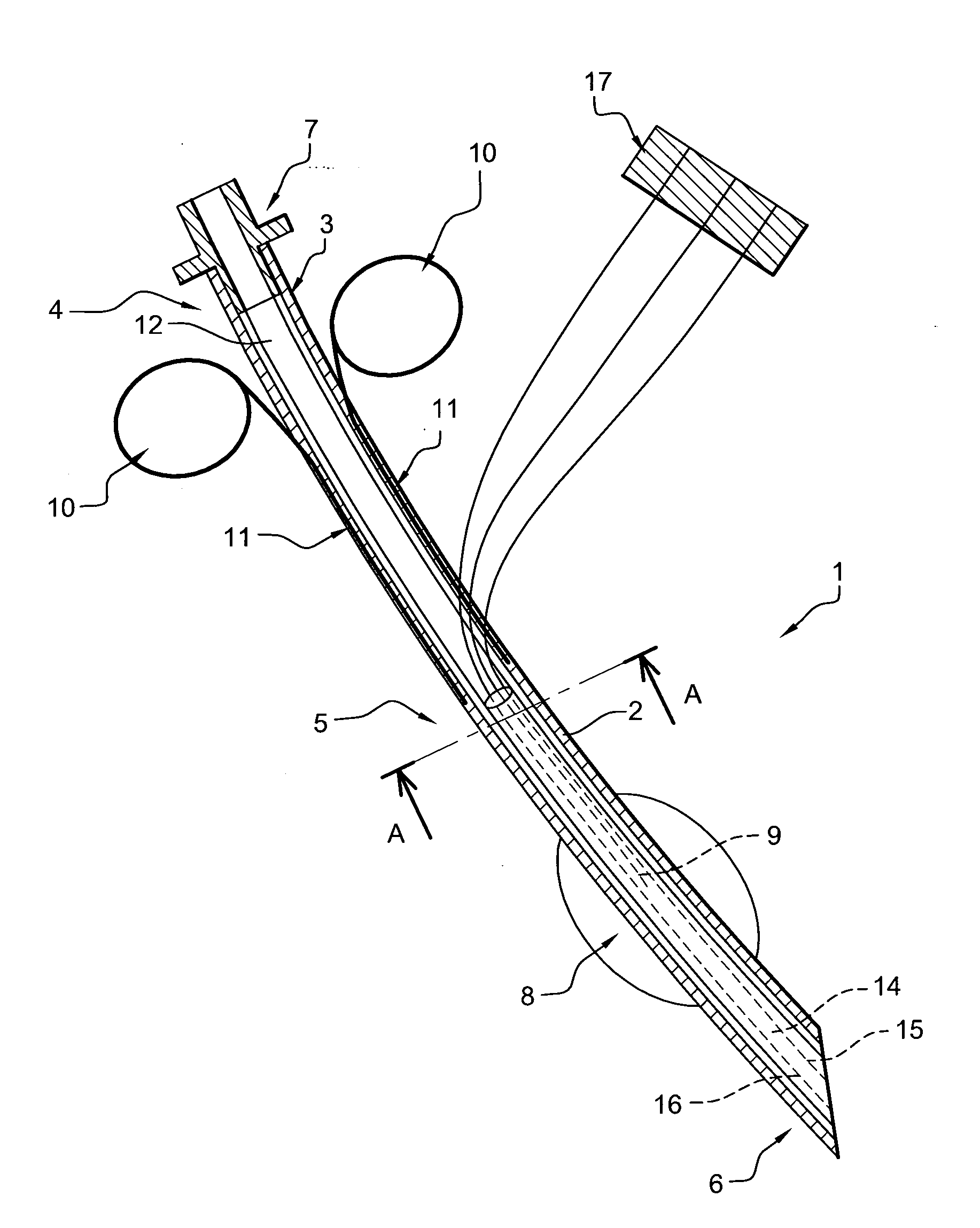
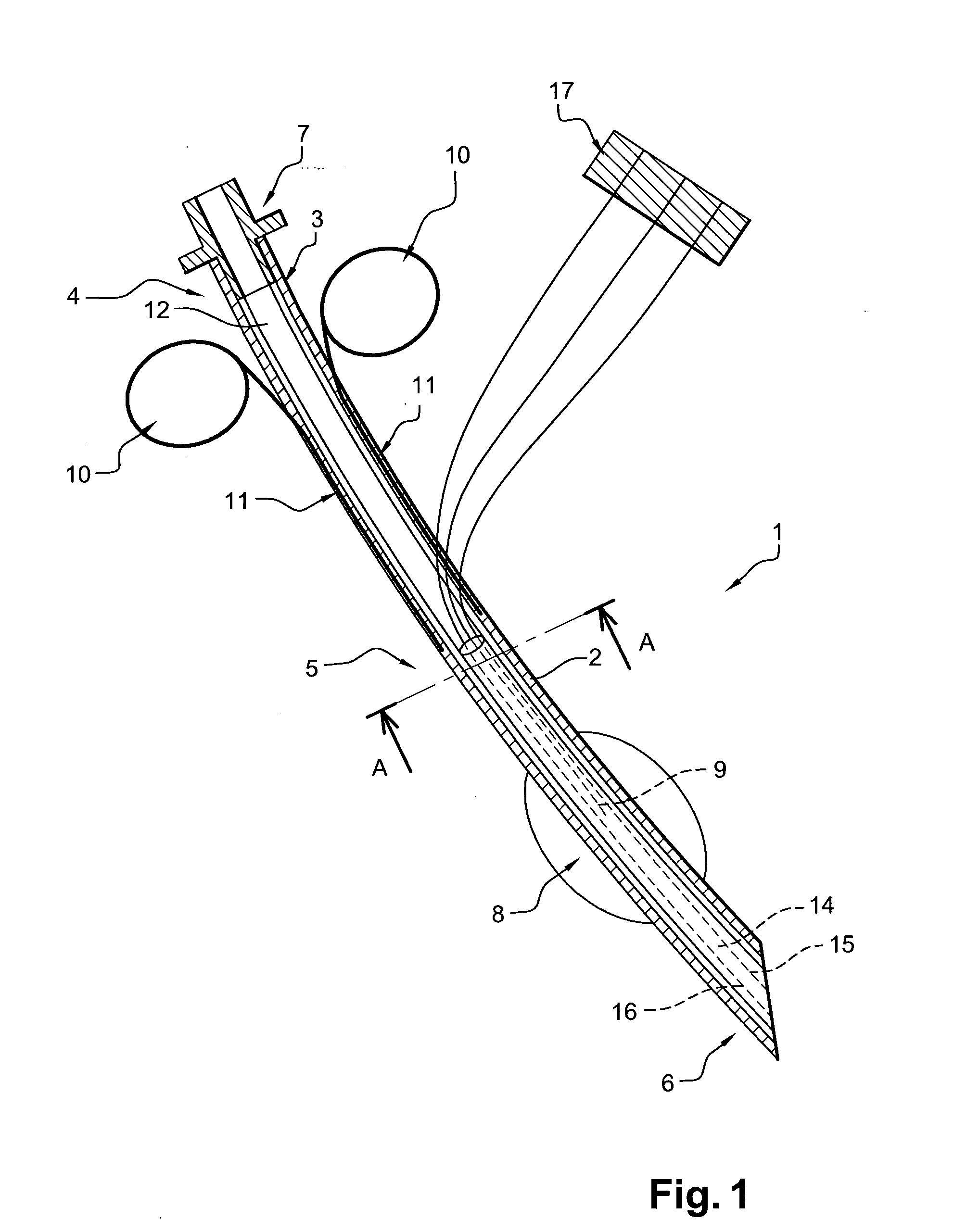
[0046]FIG. 1 shows a section view of an endotracheal intubation device 1 according to the invention. The endotracheal intubation device 1 comprises a main tube 2 having a peripheral wall 3, a proximal end portion 4, a central portion 5 and a distal end portion 6. The proximal end of said main tube 2 is provided with an adaptor 7. The endotracheal intubation device 1 comprises also a cuff 8 inflatable and disposed on the main tube 2 in sealed relation thereto adjacent to the distal end portion 6. The cuff 8 is connected to an inflation tube 9. The main tube 2 is also provided with controlling means including two manipulation rings 10 and pulling lines 11 extending from said manipulation rings 10. The peripheral wall 3 delineates a main channel 12 adapted for the air passage extending from the proximal end portion 4 to the distal end portion 6.

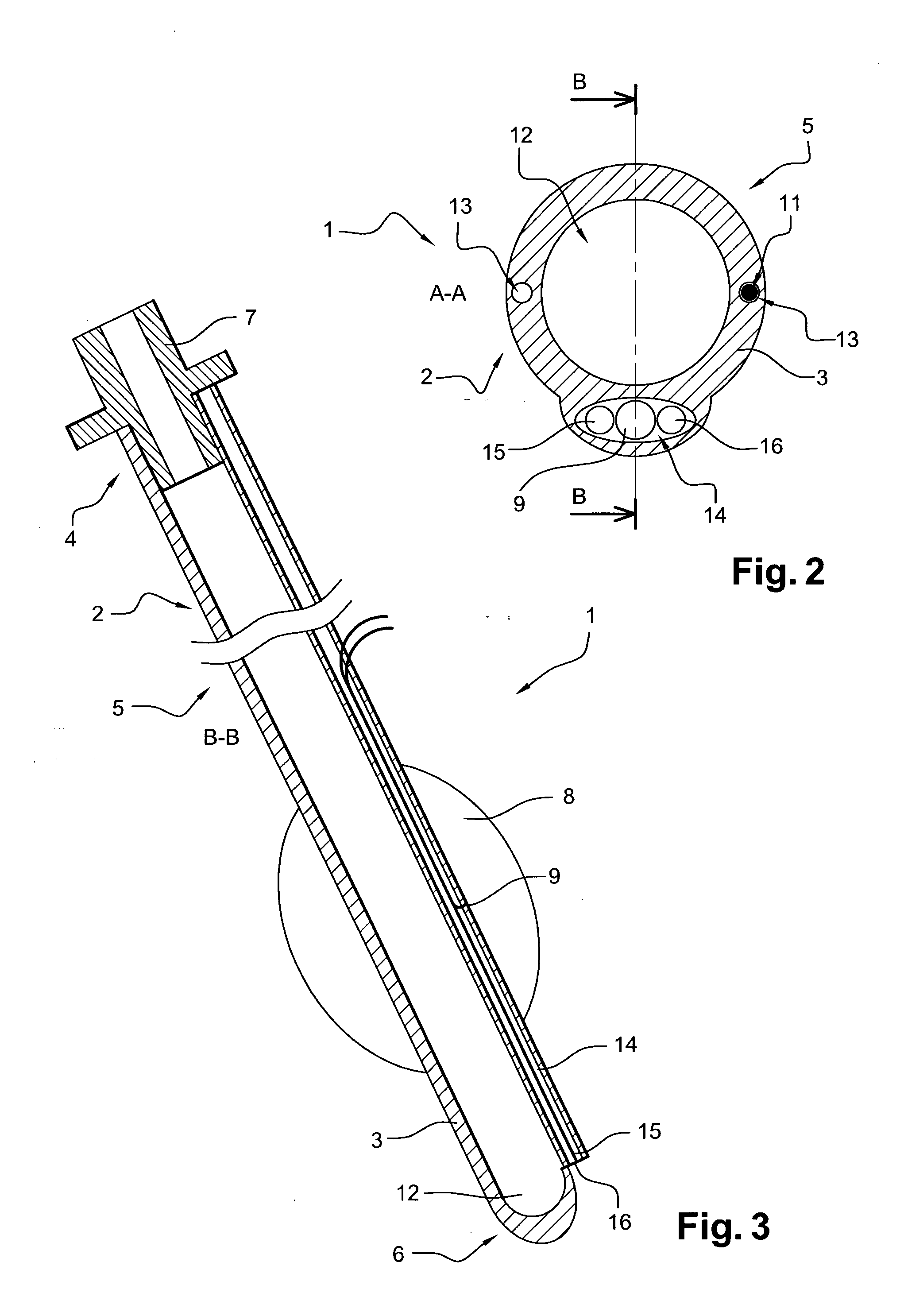
[0047]As shown on FIG. 2 and FIG. 3, each pulling line 11 is guided inside a longitudinal guiding channel 13 incorporated into the peripheral w...


PUM


Abstract

“An endotracheal intubation device includes an inflatable cuff connected to an inflation tube, visualization means, where the visualization means include means to enlighten and an image guide, where the means to enlighten, the image guide, and the inflation tube are associated to a first three ways connector adapted to connect the endotracheal intubation device to a control panel; a packaging is also provided containing the endotracheal intubation device wherein the first three ways connector is placed across the packaging so as to allow checking the endotracheal intubation device without impairing its sterility with an endotracheal intubation device tester; an intubation method is further provided using the packaging, the control panel and the endotracheal intubation device tester.”

Description

TECHNICAL FIELD[0001]The present invention relates to an endotracheal intubation device adapted for the control of upper aerial ways in reanimation or anesthesia. The present invention further relates to an assembly comprising an endotracheal intubation device and to a procedure using it.[0002]In the present application, the distal end of a component or of a device is to be understood as meaning the end furthest from the practitioner's hand during proper use and the proximal end is to be understood as meaning the end closest to the practitioner's hand during proper use.BACKGROUND[0003]An intubation is a medical act that should be done by one person under emergency conditions without neither special heavy equipment nor special room. A tube is inserted into a patient's trachea in order to ensure that the airway is not closed and that air is able to reach the lungs. Although endotracheal intubation is regarded as the most reliable available method for protecting a patient's airway, man...

Claims


Application Information

Patent Timeline
IPC IPC(8): A61B1/267A61M16/04A61B19/02A61B1/04
CPCA61B1/07A61B1/267A61M16/04A61M16/0434A61B1/00165A61M2209/06A61M16/0418A61B1/00154A61M2205/6054A61M16/0486
Inventor SUPIEZ, FREDERIC
Owner SUPIEZ FREDERIC
Why Eureka
Try Eureka