

Atraumatic stent and method and apparatus for making the same
a stent and a technology of a stent and a stent body, applied in the field of atraumatic stents and methods, apparatus and systems for making the same, can solve the problems of unfavorable variation of radial expansion or compression forces, waste of material by trimming such excess wires, and stent wires of more expensive materials, so as to achieve the effect of improving quality control
- Summary
- Abstract
- Description
- Claims
- Application Information
AI Technical Summary
Benefits of technology
Problems solved by technology
Method used
Image

Examples
embodiment 1
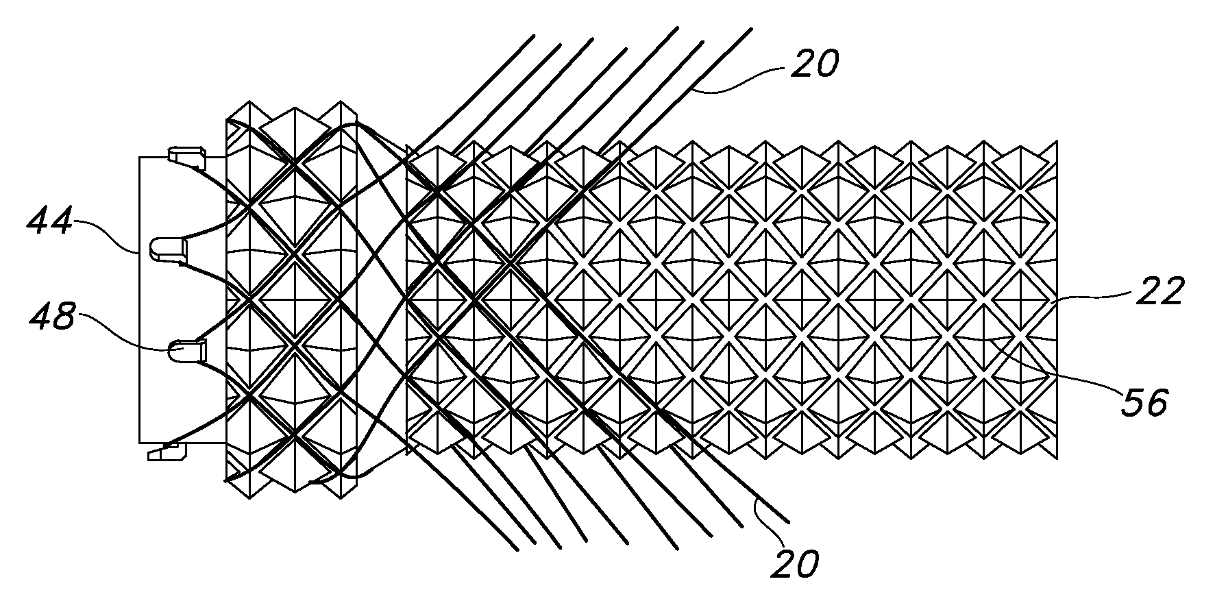
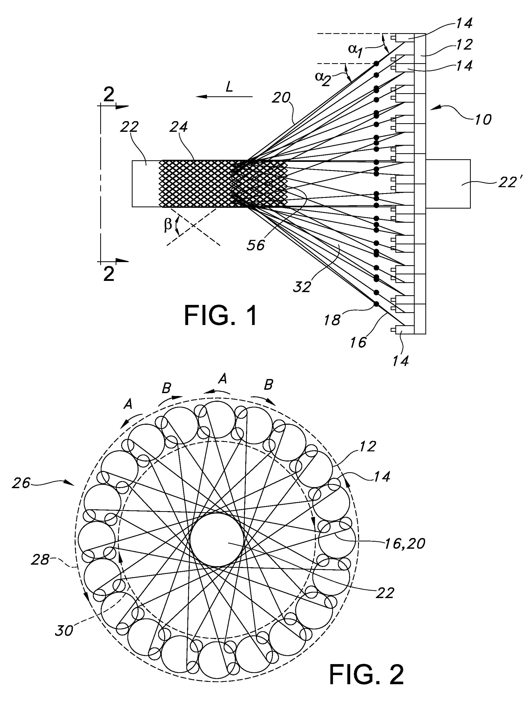
[0091]A method of braiding a stent comprising: (a) providing a number of elongate filaments, each of the filaments having opposed ends and an intermediate portion between the opposed ends; (b) providing a number of tensioned braiding carriers; (c) providing a braiding mandrel having opposed proximal and distal ends, the braiding mandrel comprising a number of circumferentially spaced-apart securement projections at the distal end of the braiding mandrel; (d) securably disposing the intermediate portion of one of the filaments to one of the securement projections; (e) securing one of the opposed ends of the one filament to one of the tensioned braiding carriers; (f) securing the other opposed end of the one filament to a different second tensioned braiding carrier; (g) repeating steps (d) through (f) until all of the intermediate portions of the filaments are securably disposed to different ones of the securement projections and until each end of the number of filaments are secured t...
embodiment 2
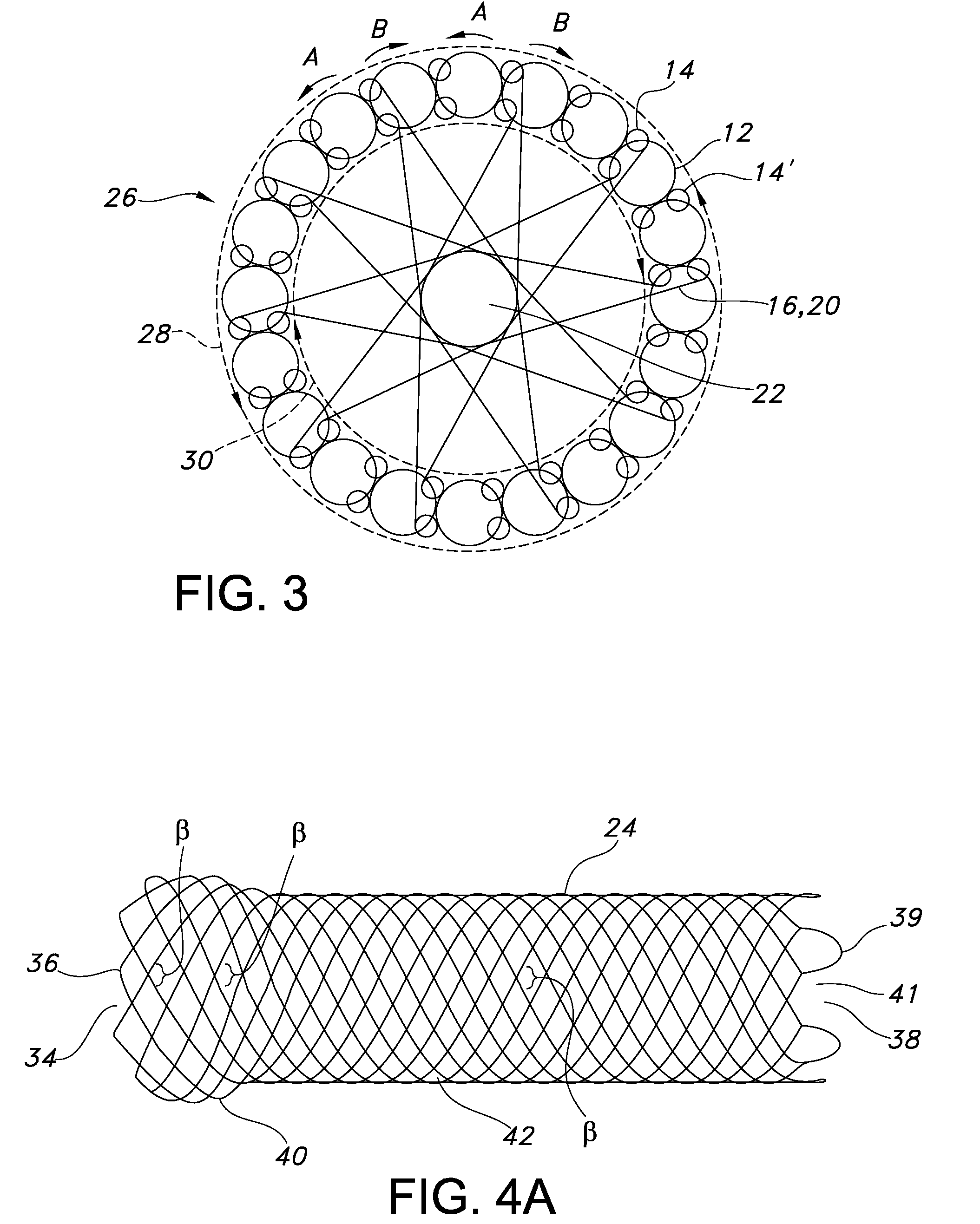
[0092]The method of embodiment 1, wherein step (h) includes moving the tensioned braiding carriers in a generally circular and serpentine motion about a circumferential plane of the mandrel.
embodiment 3
[0093]The method of embodiment 1, wherein the tensioned braiding carriers each comprise a retractable carrier filament and further wherein step (e) includes securing the one opposed end of the one filament to the retractable carrier filament of the one tensioned braiding carrier and step (f) includes securing the other opposed end of the one filament to the retractable carrier filament of the second tensioned braiding carrier.
PUM
| Property | Measurement | Unit |
|---|---|---|
| constant tension force | aaaaa | aaaaa |
| tension force | aaaaa | aaaaa |
| braiding angles | aaaaa | aaaaa |
Abstract
Description
Claims
Application Information