Key device

Active Publication Date: 2010-08-05
KK TOKAI RIKA DENKI SEISAKUSHO
View PDF8 Cites 8 Cited by
  • Summary
  • Abstract
  • Description
  • Claims
  • Application Information

AI Technical Summary

Benefits of technology

[0023]In the key device of the third aspect, the guiding portions provided in the pair of holding portions guide to hold the urging member in the pair of holding portions. For this reason, the urging member can be easily held by the pair of holding portions.
[0024]In the key device of the fourth, the seventh or the ninth aspects, the allowing member and the regulating member are fitted with each other by the fitting portion in relatively rotatable manner. For this reason, cancellation of the state in which the allowing member, the regulating member and th

Problems solved by technology

For this reason, it is difficult to assemble and mount the lifter, the lock plate and the torsi

Method used


Image

  • Key device
  • Key device
  • Key device

Examples


first embodiment

[0036]FIG. 6 shows a cross sectional view of a steering lock device 10 that serves as a key device according to a first exemplary embodiment of the present invention when seen from the left side. In the drawings, the front side of the steering lock device 10 is indicated by arrow FR, the upper side of the steering lock device 10 is indicated by arrow UP, and the right side of the steering lock device 10 is indicated by arrow RH.

[0037]As shown in FIG. 6, the steering lock device 10 according to the present exemplary embodiment is equipped with a lock body 12 that serves as an accommodating member, and a fixed piece 14 (see FIG. 5) having a substantially semi-cylinder shape is formed at the rear end of the lower side portion of the lock body 12. The bracket (not shown in the drawings) having a substantially semi-cylinder shape is mounted to the fixed piece 14. A steering post (not shown in the drawings) of a vehicle is fitted in an inner portion of the bracket and the fixed piece 14, ...

second embodiment

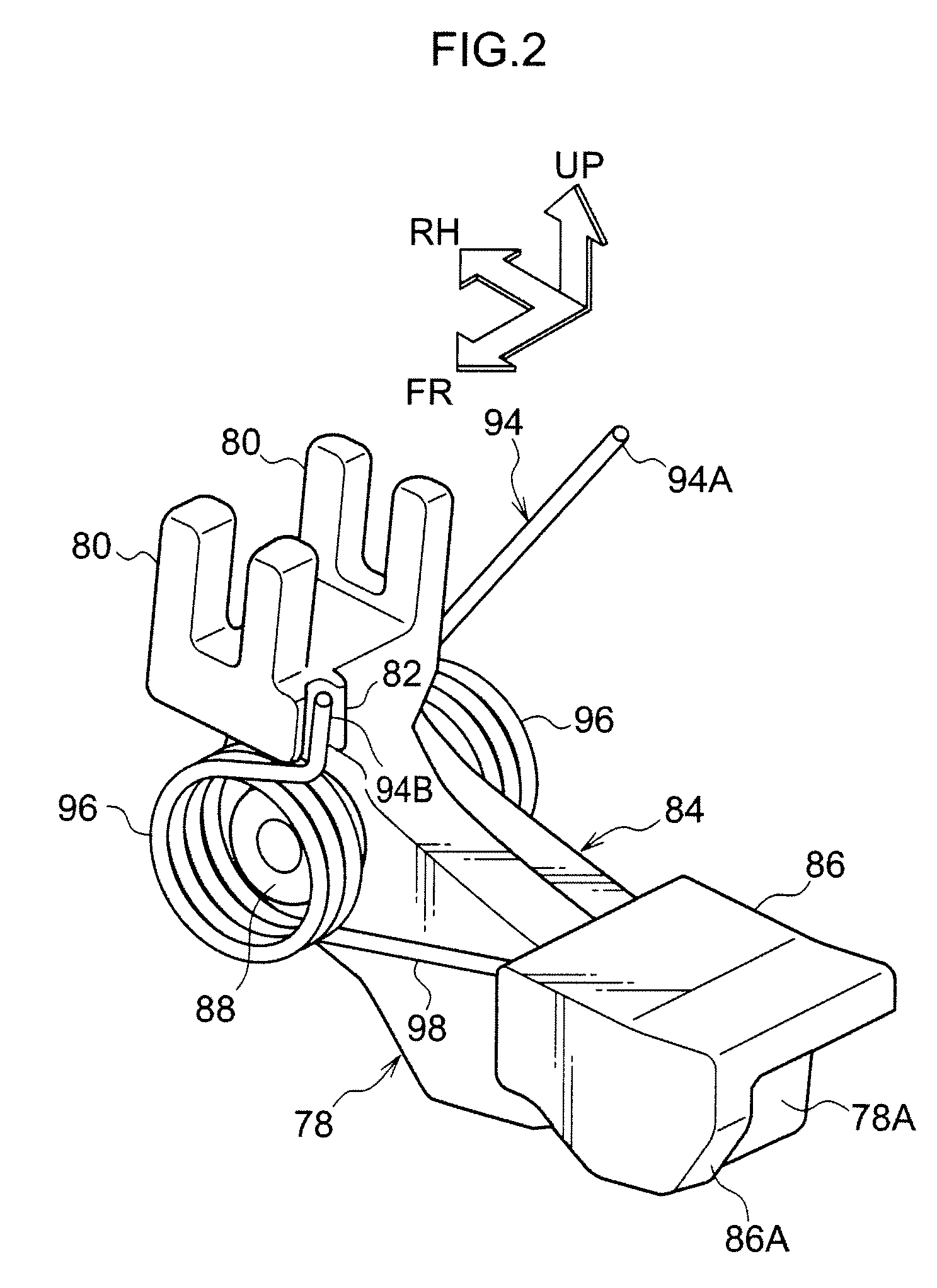
[0100]FIG. 9 shows a cross sectional view of a principal section of a steering lock device 100 that serves as a key device according to a second exemplary embodiment of the present invention when seen from the top.

[0101]The steering lock device 100 according to the second exemplary embodiment has substantially the same structure as that of the first embodiment except the following points.

[0102]As shown in FIG. 9, in the steering lock device 100 according to the second exemplary embodiment, the fitting convex portion 90 is not formed in the link 78, and the fitting concave portion 92 is not formed in the release link 84.

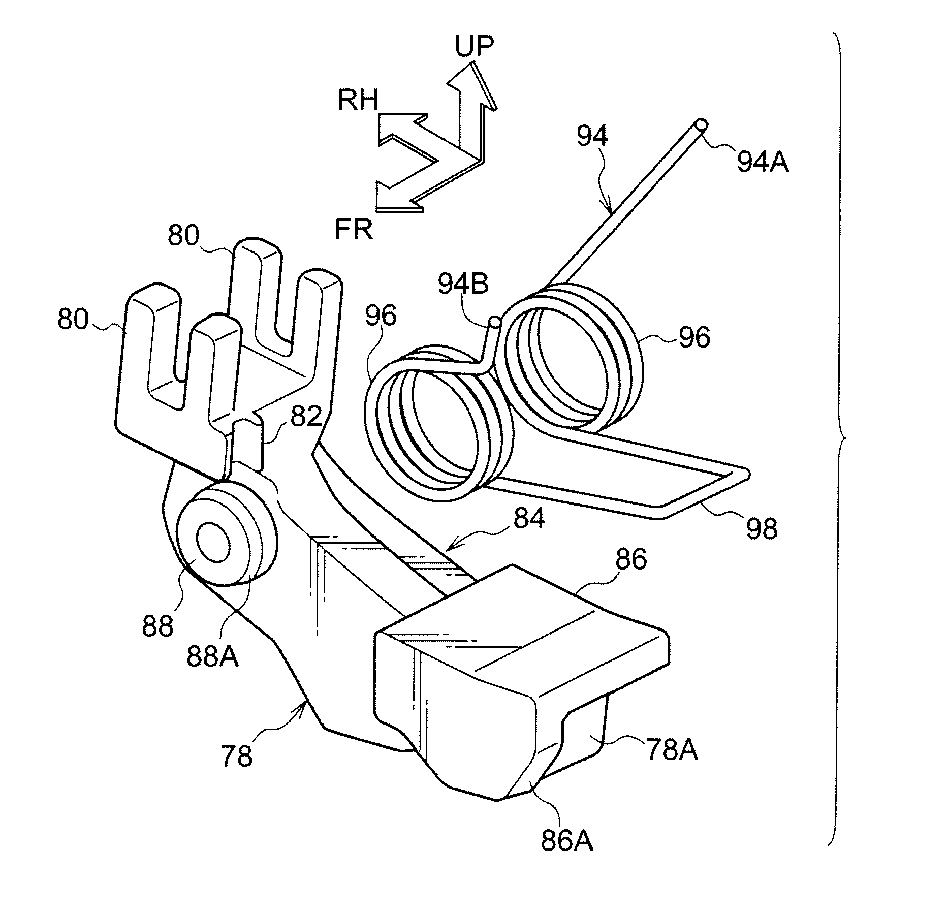
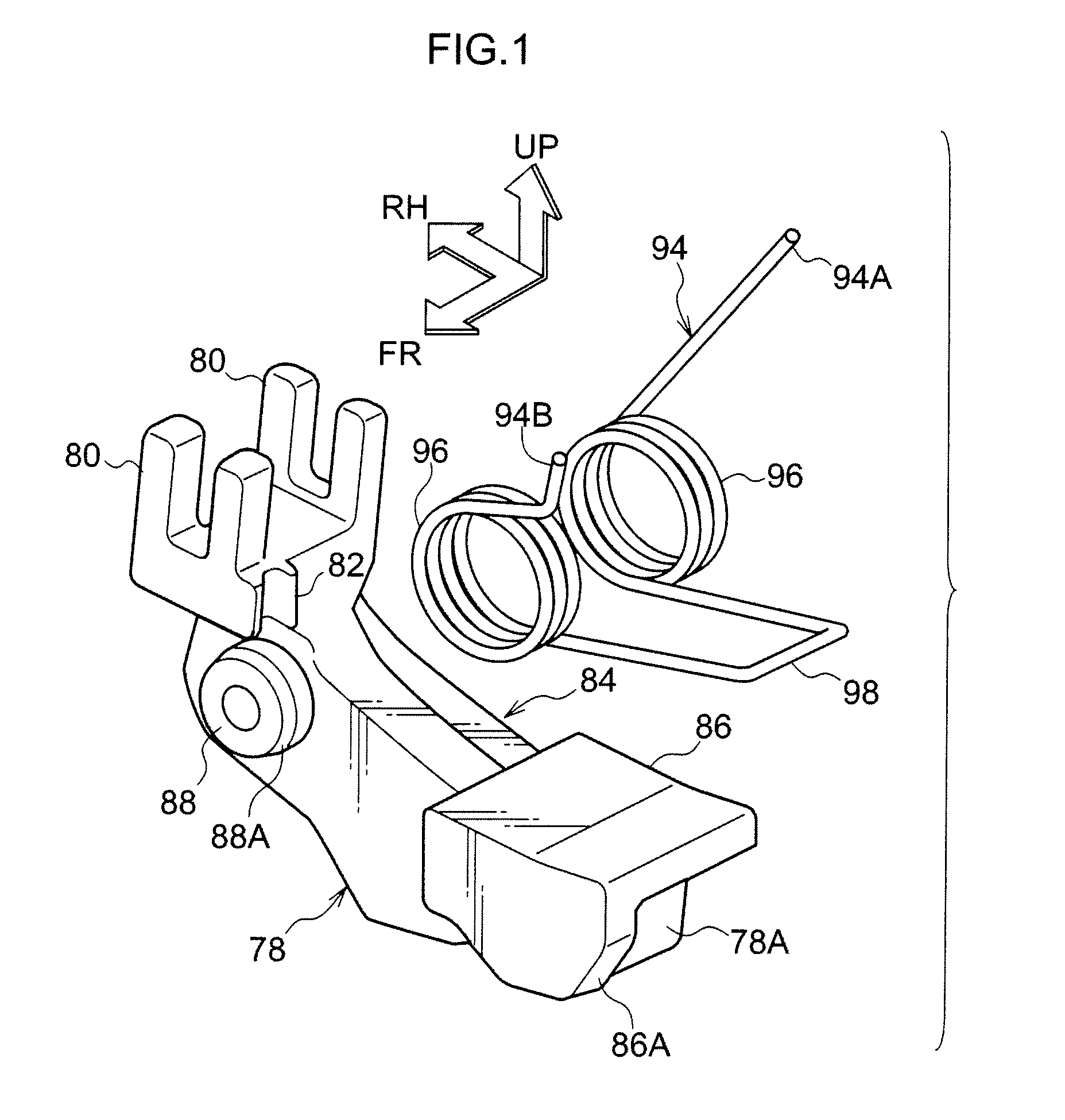
[0103]The spring holding shaft 88 is not formed integrally with the rear side surface of the release link 84, but is formed integrally with the rear side surface of the link 78, so as to provide the structure of the fitting section.

[0104]A substantially circular fitting hole 102 that forms (serves as) the fitting portion is formed in penetration manner in the release ...


PUM


Abstract

A regulating member, an allowing member and an urging member are easily assembled to a subject to which these members are assembled. When assembling of an interlock unit is carried out, with a fitting convex portion of a link being fitted into a fitting concave portion of a release link, a torsion spring (particularly, a connecting portion) is temporarily elastically deformed, and a pair of spiral portions of the torsion spring are mounted to spring holding shafts of the link and the release link, respectively. As a result, the link, the release link and the torsion spring can be brought into a temporarily assembled state, and can be easily assembled to a unit box.

Description

CROSS-REFERENCE TO RELATED APPLICATION[0001]This application claims priority under 35 USC 119 from Japanese Patent Application No. 2009-022913, the disclosure of which is incorporated by reference herein.BACKGROUND OF THE INVENTION[0002]1. Technical Field[0003]The present invention relates to a key device that regulates rotation of a key.[0004]2. Related Art[0005]There are key devices in which when a lifter is rotated by rotation of a key knob to an “ACC position”, a lock plate does not rotate together with the lifter, thereby causing rotation of the key knob to the “ACC position” to be regulated, while rotation of the key knob to the “ACC position” is permitted due to the lock plate being rotated together with the lifter (for example, refer to Japanese Patent Application Laid-Open (JP-A) No. 2000-229557).[0006]In such key device as described above, the lifter and the lock plate are supported by a support shaft in a rotatable manner, and a torsion spring is provided at the support s...

Claims


Application Information

Patent Timeline
IPC IPC(8): E05B65/00B60R25/021E05B83/00
CPCB60R25/02144Y10T70/5646Y10T70/565Y10T70/5655Y10T70/5659Y10T70/5664Y10T70/5956
Inventor NAKAMOTO, YUJI
Owner KK TOKAI RIKA DENKI SEISAKUSHO
Why Eureka
Try Eureka