
Parallel Kinematic Structure

a kinematic chain and parallel technology, applied in the field of parallel kinematic chain for a kinematic chain, can solve the problems of low mechanical eigen-frequencies, high inertia, and low stiffness

Active Publication Date: 2010-08-05
BALL CORP +1
View PDF5 Cites 41 Cited by
  • Summary
  • Abstract
  • Description
  • Claims
  • Application Information

AI Technical Summary

Benefits of technology

[0005]The object of the present invention is to provide a parallel kinematic structure having enhanced characteristics concerning fabrication, costs and operability as compared with known parallel kinematic structures.SHORT DESCRIPTION OF THE INVENTION

Problems solved by technology

Non-parallel kinematic structures providing up to 6 degrees of freedom (DOFs) usually offer large motion ranges but have a high inertia because actuators are arranged within and carried by the structure and have a low stiffness because forces and torques are transmitted through a single kinematic chain.
As a result, mechanical eigen-frequencies are commonly low.

Method used


Image

  • Parallel Kinematic Structure
  • Parallel Kinematic Structure
  • Parallel Kinematic Structure

Examples


Embodiment Construction

[0046]Before a detailed description of the accompanying drawings, some further aspects of the present invention will be discussed.

[0047]In a preferred embodiment, the planar joint arrangement may be adapted for active movements in at least one of its degrees of freedom.

[0048]In another embodiment, at least one of the anti-planar joint arrangement, the planar joint arrangement, the kinematic chains and the may be formed as monolithical part or piece.

[0049]If the parallel kinematic structure comprises one or more kinematic chains having no planar joint arrangement, at least one of the input sections of the anti-planar joint arrangement of these kinematic chains may be fixed or rigidly connected, for example to a base or support of the parallel kinematic structure.

[0050]In an embodiment, the at least one planar joint arrangement (i.e. planar joint arrangement of the at least one kinematic chain) may have a base section, which is fixed or rigidly connected, for example to a base or supp...


PUM


Abstract

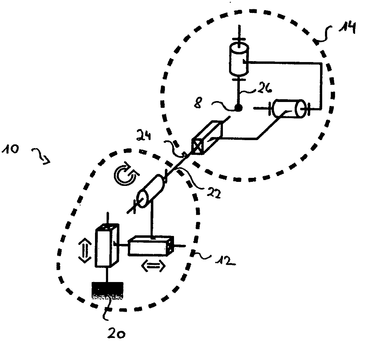
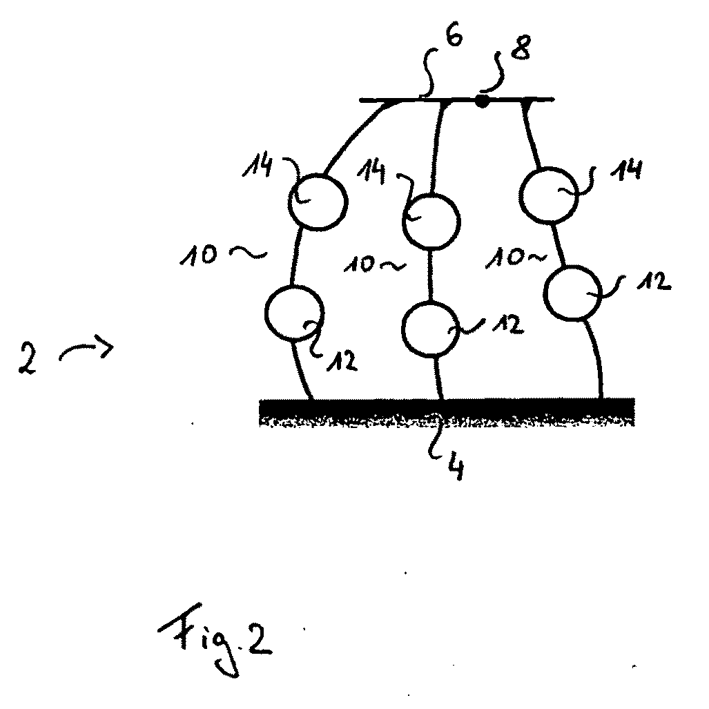
A parallel kinematic structure comprises at least two kinematic chains being functionally arranged in parallel. Each of the two kinematic chains has, at a moveable end thereof, at least one degree of freedom, and comprising a passive anti-planar joint arrangement having a translational degree of freedom and two rotational degrees of freedom. Each anti-planar joint arrangement has an input section and an output section. At least one of the kinematic chains comprises a planar joint arrangement having at least one of at least one translational degree of freedom and a rotational degree of freedom, the planar joint arrangement having an output section. Further, the planar joint arrangement is adapted for active movements in at least one of its degrees of freedom. The input section of the anti-planar joint arrangement and the output section of the respective planar joint arrangement are coupled. The parallel kinematic structure further comprises a moveable end-effector section coupled with the output sections of the anti-planar joint arrangements.

Description

FIELD OF THE INVENTION[0001]The present invention relates, in general, to kinematic structures and, in particular, a kinematic chain for a kinematic structure, which kinematic chain includes a planar joint arrangement and a passive anti-planar joint arrangement, and a kinematic structure including such kinematic chains.BACKGROUND OF THE INVENTION[0002]So-called parallel kinematic structures are known. For example, U.S. Pat. No. 6,453,566 B1, U.S. Pat. No. 6,467,762 B1, U.S. Pat. No. 6,871,584 B2, EP 218546 B1 and EP 250 470 B1 disclose structures of this type.[0003]Non-parallel kinematic structures providing up to 6 degrees of freedom (DOFs) usually offer large motion ranges but have a high inertia because actuators are arranged within and carried by the structure and have a low stiffness because forces and torques are transmitted through a single kinematic chain. As a result, mechanical eigen-frequencies are commonly low.[0004]Parallel kinematic structures also providing up to 6 DO...

Claims


Application Information

Patent Timeline
IPC IPC(8): B25J17/02
CPCB25J17/0266Y10T74/20335B25J9/0015Y10T74/20305Y10T74/20329
Inventor HELMER, PATRICKBAUR, CHARLESWEIBEL, MARC
Owner BALL CORP
Learn More