Enhanced Brake Booster Vacuum Support

a technology of brake booster and vacuum support, which is applied in the direction of fluid coupling, servomotor, coupling, etc., can solve the problems of lowering reducing so as to improve the vacuum level of brake booster and mitigate the effect of less than optimal brake pedal performan

Inactive Publication Date: 2010-08-05
GM GLOBAL TECH OPERATIONS LLC
View PDF16 Cites 15 Cited by
  • Summary
  • Abstract
  • Description
  • Claims
  • Application Information

AI Technical Summary

Benefits of technology

[0010]The present invention is a method to enhance brake booster vacuum utilizing internal combustion engines, particularly, but not limited to, SIDI engines, incorporating a supplemental brake assist system, such as the above described Low Vacuum Brake Assist (LVBA), under low brake booster vacuum level conditions, as for example previous

Problems solved by technology

Motor vehicles utilizing present day spark ignition direct injection (SIDI) engines may under certain circumstances produce a lesser than optimal vacuum level.
Correspondingly, this may result in a lower brake booster vacuum level.
During these types of events, brake booster vacuum might not achieve the minimum vacuum level threshold, and, therefore, brake pedal performance may be less than optimal.
LVBA does not produce or supply vacuum to the brake booster and, thus, does not enhance brake booster vacuum.
However, if the brake boo

Method used


Image

  • Enhanced Brake Booster Vacuum Support
  • Enhanced Brake Booster Vacuum Support
  • Enhanced Brake Booster Vacuum Support

Examples


Embodiment Construction

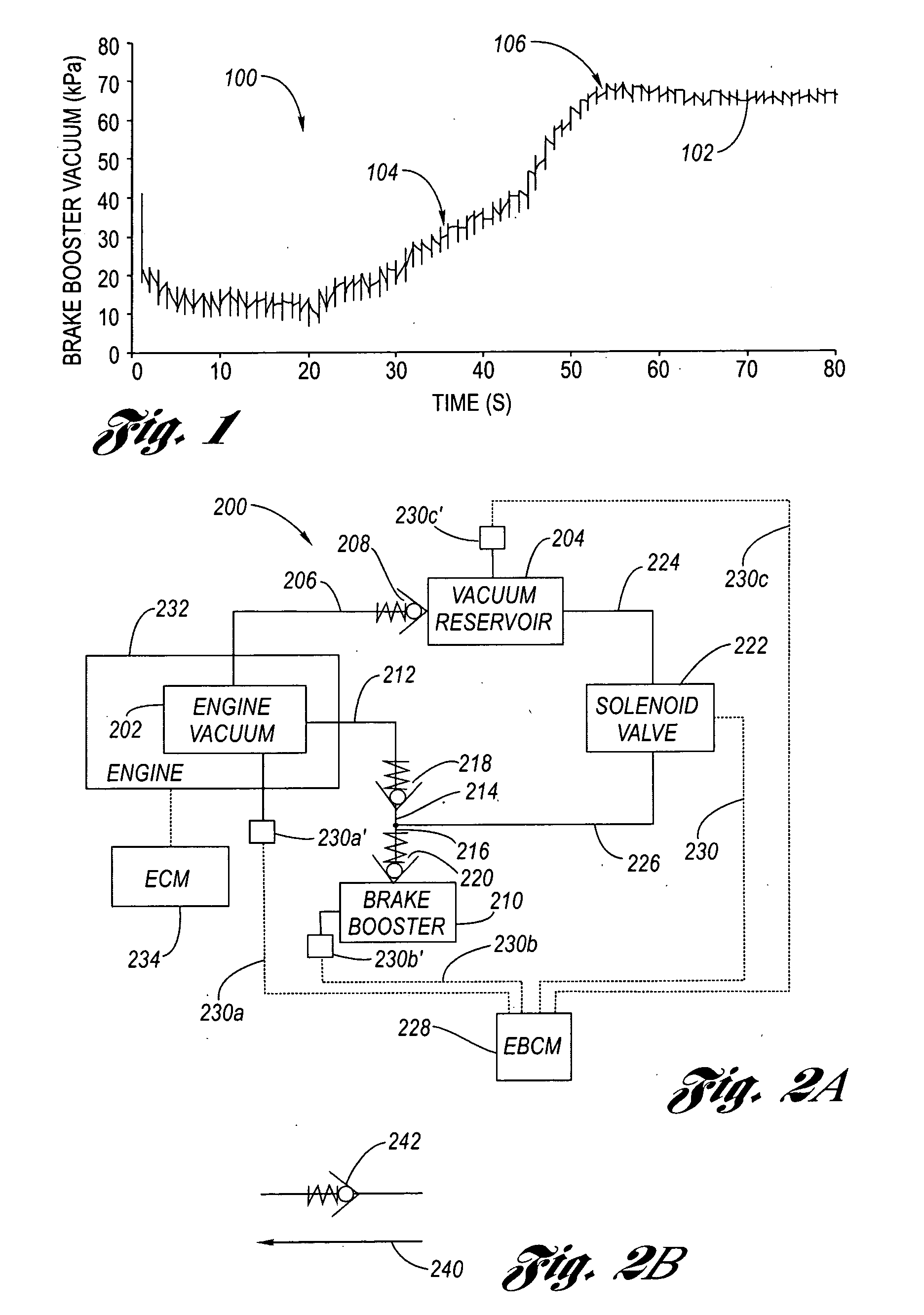
[0023]Referring now to the Drawings, FIG. 1 is a plot 100 of brake booster vacuum versus time from a cold start for a typical SIDI engine according to the prior art. In FIG. 1, the predetermined vacuum level threshold is threshold α, as for nonlimiting example approximately 30 kPa, depicted at point 104 of graph 102, whereat the time required to achieve the brake booster vacuum level of threshold α is, approximately, 37 seconds. From point 106 of graph 102 of FIG. 1, the time required to achieve a brake booster vacuum level of level β, as for nonlimiting example approximately 67 kPa is, approximately, 55 seconds. In general during a cold start event, approximately 30 to 60 seconds are necessary for present SIDI engines to produce a vacuum level for the brake booster greater than or equal to the predetermined vacuum level threshold, threshold α.

[0024]As stated hereinabove, vacuum levels, such as 30 kPa, are gage pressures as measured by a vacuum gage. That is, a vacuum gage pressure ...


PUM


Abstract

An apparatus and method for providing enhanced vacuum to a brake booster of a braking system under certain operational conditions. Vacuum is stored in a reservoir and is controllably released to the brake booster to provide a brake booster vacuum level of at least a predetermined vacuum level threshold in order to avoid brake pedal performance issues being perceived by the driver of motor vehicles utilizing engines utilizing a supplemental brake assist system under conditions where the brake booster vacuum level is less than the predetermined vacuum level threshold.

Description

TECHNICAL FIELD[0001]The present invention relates to motor vehicle brake systems incorporating vacuum brake boosters. More particularly, the present invention relates to a method of enhancing brake booster vacuum for motor vehicles utilizing internal combustion engines, particularly, but not limited to, spark ignition direct injection (SIDI) engines.BACKGROUND OF THE INVENTION[0002]Motor vehicles utilizing present day spark ignition direct injection (SIDI) engines may under certain circumstances produce a lesser than optimal vacuum level. Correspondingly, this may result in a lower brake booster vacuum level. When the brake booster vacuum level is less than a minimum vacuum level threshold, changes in brake pedal performance can be discerned by the driver (i.e., harder than normal brake pedal feel, pedal pulsation, etc.). There are many contributors to low powertrain vacuum generation, however the most predominate, in relation to brake booster vacuum levels, are engine cold start a...

Claims


Application Information

Patent Timeline
IPC IPC(8): B60T13/56B60T13/57B60T13/68
CPCB60T13/57B60T17/06B60T13/72
Inventor CALNEK, SCOTTOSTAN, TERRY W.
Owner GM GLOBAL TECH OPERATIONS LLC
Why Eureka
Try Eureka